Abstract
Techniques for spherical osteotomy, such as rotational acetabular osteotomy, can help orthopaedic surgeons correct bony deformities and remove spherical acetabular components. Curved chisels are used during a spherical osteotomy, but they require skill and have a potential risk of damaging blood vessels or nerves. In order to perform a precise, quick and safe spherical osteotomy, we have developed a novel computer-assisted surgical tool using a vibrating bone saw, the Tuke Saw®, with a curved blade that operates under the guidance of an optical navigation system. In this study, the accuracy and ease of use of this curved-bladed Tuke Saw® in spherical osteotomy were examined in comparison with the conventional curved chisel. Using these surgical tools, hemispherical osteotomies were performed on rectangular parallelepiped Sawbones® blocks and rotational acetabular osteotomies were performed on cadaveric pelves. The distance error with the curved-bladed Tuke Saw® was significantly smaller than that with the curved chisel, and the procedure time with the Tuke Saw® was approximately half that with the chisel. It can thus be concluded that the curved-bladed Tuke Saw® is more accurate and easier to use than the conventional curved chisel.
Introduction
Techniques for cutting bone spherically (spherical osteotomy) are required for various orthopaedic surgeries such as rotational acetabular osteotomy Citation[1] (), Wagner's spherical osteotomy of the acetabulum Citation[2], or revision of well-fixed cementless acetabular sockets in total hip arthroplasty Citation[3]. In addition, these techniques can be used for corrective osteotomy around the knee joint in cases of osteoarthritis, though complete spherical osteotomy has not yet been performed for the knee joint due to the technical difficulties associated with this method.
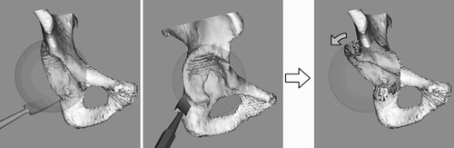
Figure 1. Rotational acetabular osteotomy (spherical type) with a conventional curved chisel.
Conventionally, curved chisels have been used for such spherical osteotomy. However, it is not easy to control the tip of the chisel blade precisely even under fluoroscopic guidance. Moreover, intrapelvic vessels cannot be seen directly, so there is a risk of injury Citation[4]. Vascular injuries around the hip joint have been reported by Tönnis et al. in triple pelvic osteotomy Citation[5], by Davey et al. in periacetabular osteotomy Citation[6], and by Sharma et al. in primary and revision total hip arthroplasty Citation[7].
To perform precise osteotomy and avoid risks, navigation systems have been introduced to osteotomy surgery Citation[8]. Such systems enable real-time tracking of chisels and visualization of their tips. Navigation systems have been effective to some extent, but the risk of vascular injury still remains due to the sharp cutting edges of the chisels.
In order to perform a precise, quick and safe spherical osteotomy, we developed a surgical navigation system with a curved-blade vibrating bone saw (). This bone saw (Tuke Saw®) has a safety feature that prevents damage to soft tissues by limiting the diameter of its circular movement to only 1.5 mm. The purpose of the present study was to compare the accuracy and ease of use of this novel curved-bladed Tuke Saw® with those of the conventional curved chisel in spherical osteotomy, both under CT-based navigation.
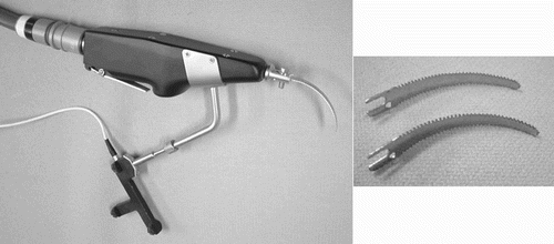
Figure 2. Curved-bladed Tuke Saw fitted with a tracker for the optical navigation system.
Materials and methods
To compare the accuracy and ease of use of the Tuke Saw® with those of the conventional curved chisel in spherical osteotomy under CT-based navigation, two sets of experiments were conducted. First, to simply compare the design features of these surgical tools, a hemispherical osteotomy was performed on rectangular parallelepiped Sawbones® blocks using each tool under navigation. In the next experiment, as a preclinical study, rotational acetabular osteotomy (spherical type) was performed on cadaveric pelves using the curved-bladed Tuke Saw® on one side of the hemipelvis and the curved chisel on the other side, again under navigation guidance. To evaluate accuracy, the distance error of the actual osteotomy surface from the planned sphere was measured. For the usability test, procedure time and average thickness of bone loss (in the Sawbones® study only) were measured.
The CT-based optical surgical navigation system used in this study was developed in our institute Citation[9]. This system consists of an optical three-dimensional (3D) position-tracking sensor (OPTOTRAK® 3020, Northern Digital Inc., Waterloo, Ontario, Canada), an OPTOTRAK® pen-probe with 24 infrared light-emitting diode (LED) markers, active trackers with 15 infrared LED markers (AdapTrax®, Traxtal Technologies, Toronto, Ontario, Canada), and a Solaris 2.6 computer workstation (Sun Microsystems, Inc., Santa Clara, CA). Real-time tracking of surgical tools on the computer monitor was enabled with this navigation system.
An optical navigation tracker was attached to a Tuke Saw®, (Finsbury Instruments, Leatherhead, UK) an air-powered vibrating bone saw (). After calibration of the saw blade using a paired-point matching technique and registration of the target object with the tracker, the position of the saw and target object were visualized on the navigation monitor (, left). The standard Tuke Saw® has a straight blade for planar osteotomy, which it rotates and oscillates at 2000 cycles/min with a range of 1.5 mm. Because the range of the blade's circular motion is only 1.5 mm, it has a safety feature that makes it hard to cut soft tissues. The blade is changeable, and a curved blade with various radii, lengths or thicknesses can be attached. Curved saw blades for spherical osteotomy were made by bending standard blades.
Figure 3. Hemispherical osteotomy with curved-bladed Tuke Saw® (left) or curved chisel (right) under optical navigation.
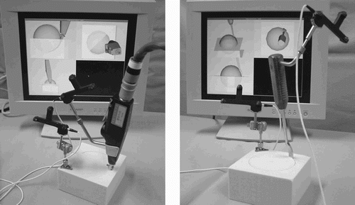
For the conventional curved chisel, Tagawa's curved osteotomes Citation[1] were used. These chisels are usually used for rotational acetabular osteotomy. An optical navigation tracker was attached to a curved chisel and surgical navigation was enabled (, right).
Hemispherical osteotomy on Sawbones® blocks
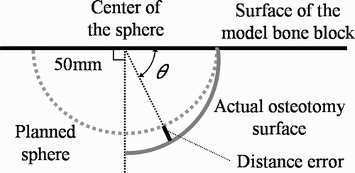
As a model of cancellous bone, Sawbones® rectangular parallelepiped blocks of cellular solid polyurethane foam (14 × 14 × 7 cm in size, 0.16 g/cm3 in density) (Pacific Research Laboratories, Vashon, WA) were used. The planning of the hemispherical osteotomy for the model bone block was made with the center placed on the surface of the block and a radius of 50 mm ( and ). The curved-bladed Tuke Saw® and the curved chisel, both with a blade of the same radius as that of the planned sphere (50 mm), were used to perform a hemispherical osteotomy. Active trackers for the navigation system were attached to the rim of the model bone block and to the surgical tool. Hemispherical osteotomy for the block was performed with each of the surgical tools under navigation (). The osteotomy was performed by three specialist hip surgeons among the authors of this paper.
Figure 4. Evaluation of actual osteotomy surface.
After the osteotomy, CT images of the cut blocks were obtained with 1 mm thickness and 1 mm pitch and with a field of view of 42 cm. Polygonal 3D surface models of the actual osteotomy surface were made from the CT images with DICOM viewer software (Virtual Place™ M, Aze Ltd., Tokyo, Japan) using the Marching Cubes method Citation[10]. The measurements were performed with these polygonal 3D surface models on a computer using the Visualization Toolkit (VTK) libraries (Kitware Inc., Clifton Park, NY).
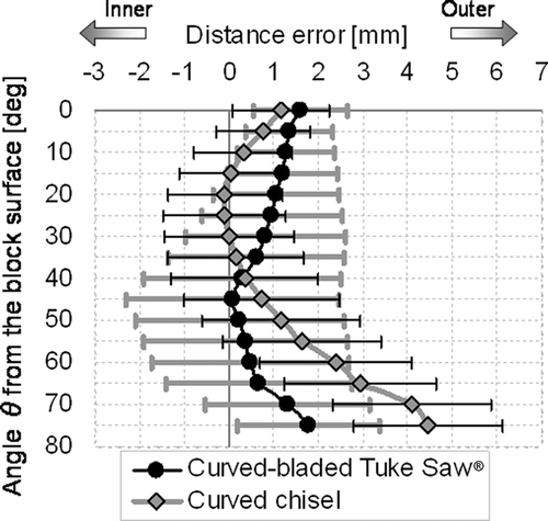
Distance error for the actual osteotomy surface was evaluated at the depth of an angle θ from the block surface (). The angle θ was defined as the latitude of the planned sphere from the block surface. The angle θ is 0° if the position is on the block surface and 90° if the position is at the pole of the planned sphere, i.e., at the greatest depth below the block surface. On a computer, a conic surface of latitude angle θ with its vertex placed at the center of the planned sphere was simulated and the 3D surface model of the actual osteotomy surface was cut with this conic surface. Then, the sectional annular line was obtained and the coordinates of the points of this sectional line were used for calculation of the distance error from the planned sphere to the actual osteotomy. The average distance error was calculated by proportional distribution of the length of the line segment element of the sectional line. The distance error was defined as positive if the position was outside the planned sphere, and negative if the position was inside the sphere. The distance error of the actual osteotomy surface from the planned sphere was measured every 5° of the angle θ from 0° to 75°.
The volume and average thickness of bone loss were calculated from the weight loss of the model bone block. The weight loss was measured with an electronic balance and the volume of bone lost was obtained by dividing the weight loss by the density of the block. The surface area of the actual osteotomy surface was calculated from the 3D surface model, then the average thickness of bone loss was calculated by dividing the volume by the surface area. The procedure time for each hemispherical osteotomy was also measured.
The trials of hemispherical osteotomy were performed five times for each surgical tool by each of the three surgeons. That is, a total of 15 trials were performed for each surgical tool. Statistical analyses were performed using Student's unpaired t-test with a significance level of 0.05.
Rotational acetabular osteotomy on cadaveric pelves
Eight normal cadaveric pelves were used. CT images of the pelves were obtained with 1 mm thickness and 3 mm pitch with a field of view of 42 cm. Preoperative polygonal 3D surface models of the pelves were made from the CT images with the abovementioned DICOM viewer using the Marching Cubes method.
Preoperatively, a spherical type of rotational acetabular osteotomy was planned for each hemipelvis with an adequate radius and position according to the individual size and position of each acetabulum. The radius of the planned sphere of the osteotomy was set to be 15 mm larger than the radius of the acetabulum, and the center of the planned sphere was basically placed on the center of the acetabulum. (The position of the planned center was adjusted within 3 mm if the posterior column of the hemipelvis was too thin.) The average radius of the acetabulum for all hemipelves was 25.6 mm (range: 23.5–28.0 mm), and the difference in radius of the acetabulum between the right and left sides of the same pelvis was within 1 mm for all pelves. The average radius of the planned sphere of the osteotomy was 40.6 mm (range: 38.5–43.0 mm) for all the hemipelves.
For each pelvis, rotational acetabular osteotomy was performed with the curved-bladed Tuke Saw® on one side of the hemipelvis and with the curved chisel on the other side. For all the hemipelves, a curved blade with a 50-mm radius was selected and used. Considering the planned radii of the osteotomy in these cadaveric pelves (average 40.6 mm), a smaller blade radius was naturally desired, but although a blade of 40 mm-radius is available for the curved-bladed Tuke Saw®, Tagawa's osteotomes only provide chisels with blades of radius 50 mm or 60 mm. Therefore, to make a fair comparison between both systems, a blade with 50-mm radius was used to perform all the osteotomies.
Two of the specialist hip surgeons among the authors performed rotational acetabular osteotomy under CT-based navigation in a manner similar to that used during the above mentioned Sawbones® blocks experiment. Active trackers were attached to the hemipelvis and to the surgical tool. Registration of the 3D model of the hemipelvis to the real object was done using the iterative closest-point (ICP) algorithm Citation[11] with the least-square method, sampling 30 points on the surface of the real object. This is a very common method of registration in computer-assisted surgery. The surgeon manipulated the surgical tool by watching the tip of the curved blade on a computer display.
After osteotomy, CT images of the cut pelves were obtained with 1 mm thickness and 3 mm pitch, with a field of view of 42 cm. Postoperative polygonal 3D surface models of the cut pelves were made from the CT images using the DICOM viewer software mentioned above. The postoperative 3D models were superimposed on the preoperative 3D models with the registration method using the ICP algorithm with the least-square method, sampling 30 points for each fragment of the cut pelves. The root mean square (RMS) error of the registration was within 0.4 mm in all cases. The postoperative 3D models after registration were confirmed as matched with the preoperative 3D models on a computer display. After registration, the osteotomy surfaces were extracted from the postoperative 3D models, and these polygonal 3D models of the osteotomy surface were used for measurements.
The distance error of the osteotomy surface from the planned sphere was then calculated based on the polygonal 3D model of the osteotomy surface for each hemipelvis. The RMS of the distance error was calculated by proportional distribution of the surface areas of the element polygons. The RMS of the distance error of the osteotomy surface from the planned sphere was calculated for each hemipelvis. The procedure time for each hemispherical osteotomy was also measured.
Statistical analyses were performed using Student's paired t-test with a significance level of 0.05.
Results
Hemispherical osteotomy on Sawbones® blocks
The distance error of the actual osteotomy surface from the planned sphere is shown in . With both the surgical tools, the distance error became progressively larger outward from the planned sphere, as the blade went deeper into the model bone block. At positions greater than 50° from the surface of the block, the distance error for the curved-bladed Tuke Saw® was significantly smaller than that for the curved chisel (p < 0.05).
Figure 5. Distance error of actual osteotomy surface from planned sphere in Sawbones® block experiment.
The procedure time, volume of bone loss, and average thickness of bone loss for hemispherical osteotomy of the Sawbones® block are shown in . The procedure time with the curved-bladed Tuke Saw® was significantly shorter than that with the curved chisel (p < 0.05). The average thickness of bone loss with the curved-bladed Tuke Saw® was approximately 1.5 mm, and this value is approximately three times as large as that with the curved chisel.
Table I. Procedure time, volume of bone loss, and thickness of bone loss for hemispherical osteotomy in the Sawbones® block experiment (mean ± SD)
Rotational acetabular osteotomy on cadaveric pelves
The RMS of the distance error of the osteotomy surface from the planned sphere and the procedure time for the rotational acetabular osteotomy of the cadaveric pelves are shown in . The RMS of the distance error of the osteotomy surface from the planned sphere was significantly smaller with the curved-bladed Tuke Saw® than with the curved chisel (p < 0.05). No significant difference in procedure time was found for the two surgical tools (p = 0.14).
Table II. RMS of distance error of osteotomy surface from planned sphere, and procedure time for rotational acetabular osteotomy of cadaveric pelves (mean ± SD).
Discussion
A few studies on computer-assisted osteotomies have reported that navigation systems for osteotomies are useful, reduce risk and increase safety and accuracy Citation[8], Citation[12]. However, no study has quantitatively evaluated the accuracy, feasibility or safety of osteotomies. In addition, to our knowledge, there has been no study evaluating the accuracy of osteotomy surfaces. The present study analysed osteotomy surfaces three-dimensionally and evaluated quantitatively the accuracy and ease of use of a spherical osteotomy under guidance from a navigation system.
In the Sawbones® block experiment, the distance error of the actual osteotomy surface from the planned sphere was significantly smaller with the curved-bladed Tuke Saw® than with the curved chisel at positions where the angle θ was more than 50° from the surface of the block, and the average error was within 2 mm (). In the cadaver experiment, the RMS of the distance error of the osteotomy surface from the planned sphere with the curved-bladed Tuke Saw® was 2.5 mm and significantly smaller than that with the curved chisel (). Therefore, it can be said that the accuracy of the curved-bladed Tuke Saw® is higher than that of the curved chisel.
Average procedure time with the curved-bladed Tuke Saw® was less than half of that with the curved chisel in the Sawbones® block experiment (). On the other hand, no significant difference was found between the two surgical tools for the procedure time in the cadaver experiment (). This is probably because in the situation simulating actual surgery the procedure time was affected by factors other than the actual osteotomy itself, such as detachment of the periosteum or slipping of the vibrating Tuke Saw® blade on the bone surface. However, the ease of use of the curved-bladed Tuke Saw® seemed to be comparable to or better than that of the curved chisel.
The average thickness of bone loss with the curved-bladed Tuke Saw® was approximately 1.5 mm, which is approximately three times as large as that with the curved chisel () in the Sawbones® block experiment. This difference derived from the cutting mechanism of the saw, whose blade circulates with a diameter of 1.5 mm. This might represent a disadvantage of the curved-bladed Tuke Saw® in comparison to the curved chisel. However, the value of 1.5 mm is considered acceptable for clinical use, because the standard Tuke Saw® (i.e., without a curved blade) does not exhibit any problems when used for planar osteotomy.
As for safety, chisels have a potential risk of damaging blood vessels or nerves, and this risk increases as the blade tip goes deeper into the bone and can no longer be viewed directly by the surgeon. For this reason, we have been using a CT-based navigation system that enables real-time tracking of the chisel for spherical osteotomy. However, the chisel itself has a potential risk of causing neurovascular injury even when under direct view, and this risk is not eliminated by use of the navigation system. In contrast, the Tuke Saw® is a vibrating bone saw, whose risk of damaging the surrounding soft tissues is lower than that of the chisel and more similar to that of a cast cutter. In this study, the accuracy with the Tuke Saw® was significantly higher than that with the chisel at positions deeper than 50° below the surface of the block. This is important from the viewpoint of safety: The Tuke Saw® can reduce the risk of intrapelvic vascular injuries when the deep part of the bone is being cut.
One disadvantage of the Tuke Saw® is that the bone surface can be cut less easily than with the chisel. This is because the vibrating saw blade may slip on the bone surface, and because the cortical bone is hard. In the Sawbones® block experiment, no significant difference in accuracy was found between the two surgical tools at shallow positions where the angle θ from the surface was less than 50°. Therefore, it may be feasible to cut the bone at or near the surface with the chisel then use the Tuke Saw® to cut the deeper part of the bone.
The advantages of spherical osteotomy are that the osteotomy sites have large contact areas, and that the released bone fragment can be corrected in any direction. Rotational acetabular osteotomy is a type of spherical osteotomy that is often performed to treat hip dysplasia, and clinical results for this procedure have been satisfactory in most cases Citation[13], Citation[14]. Precise spherical osteotomy can also be beneficial in resecting well-fixed cementless acetabular sockets by minimizing loss of bone stock and facilitating stable fixation of revised acetabular sockets. However, conventional surgical procedures based on surgeons' experience and skill, or performed under 2D fluoroscopic guidance, are limited in their ability to accomplish such precise 3D surgical maneuvers.
From the present results, we consider that a computer navigation system in combination with the special curved-bladed Tuke Saw® tool is easy to use and will enhance surgical accuracy, providing satisfactory clinical outcomes while preventing critical neurovascular complications in spherical osteotomies.
Acknowledgements
This study was supported by the Future Pioneering Study Promotion Project of the Japan Science Promotion Council entitled “The Development of the Robotic System in the Area of the Science of Surgery”.
References
- Ninomiya S, Tagawa H. Rotational acetabular osteotomy for the dysplastic hip. J Bone Joint Surg Am 1984; 66: 430–436
- Wagner H. Experiences with spherical acetabular osteotomy for the correction of the dysplastic acetabulum. Progress in Orthopaedic Surgery, U H Weil. Springer, Berlin 1973; 2: 131–145
- Mitchell P A, Masri B A, Garbuz D S, Greidanus N V, Wilson D, Duncan C P. Removal of well-fixed, cementless, acetabular components in revision hip arthroplasty. J Bone Joint Surg Br 2003; 85: 949–952
- Kambe T, Naito M, Asayama I, Koga K, Fujisawa M, Yamaguchi T, Yatsunami M. Vascular anatomy for rotational acetabular osteotomy: cadaveric study. J Orthop Sci 2003; 8: 323–328
- Tönnis D, Arning A, Bloch M, Heinecke A, Kalchschmidt K. Triple pelvic osteotomy. J Pediatr Orthop B 1994; 3: 54–67
- Davey J P, Santore R F. Complications of periacetabular osteotomy. Clin Orthop 1999; 363: 33–37
- Sharma D K, Kumar N, Mishra V, Howell F R. Vascular injuries in total hip replacement arthroplasty: a review of the problem. Am J Orthop 2003; 32: 487–491
- Langlotz F, Bachler R, Berlemann U, Nolte L P, Ganz R. Computer assistance for pelvic osteotomies. Clin Orthop Relat Res 1998; 354: 92–102
- Sugano N, Sasama T, Sato Y, Nakajima Y, Nishii T, Yonenobu K, Tamura S, Ochi T. Accuracy evaluation of surface-based registration methods in a computer navigation system for hip surgery performed through a posterolateral approach. Comput Aided Surg 2001; 6: 195–203
- Lorensen W E, Cline H E. Marching Cubes: a high resolution 3D surface construction algorithm. ACM Computer Graphics 1987; 21: 163–169
- Besl P J, McKay N D. A method for registration of 3-D shapes. IEEE Trans Patt Anal Machine Intell 1992; 14: 239–256
- Mayman D J, Rudan J, Yach J, Ellis R. The Kingston periacetabular osteotomy utilizing computer enhancement: a new technique. Comput Aided Surg 2002; 7: 179–186
- Nakamura S, Ninomiya S, Takatori Y, Morimoto S, Umeyama T. Long-term outcome of rotational acetabular osteotomy: 145 hips followed for 10–23 years. Acta Orthop Scand 1998; 69: 259–265
- Nozawa M, Shitoto K, Matsuda K, Maezawa K, Kurosawa H. Rotational acetabular osteotomy for acetabular dysplasia. A follow-up for more than ten years. J Bone Joint Surg Br 2002; 84: 59–65