Abstract
The aim of this research is to provide a light and easy-handling shoulder model for surgeons in order to ease the preoperative and peroperative work required when replacing the shoulder joint with a prosthesis. The digital mock-up of the shoulder is simplified according to the criteria of the surgeon, allowing easy manipulation of the model for a virtual operation. The model can be parameterized from X-rays or CT images. This paper describes the method used to obtain a virtual mock-up that is useful for preoperative simulation. Furthermore, it is shown that a real-time augmented reality system could be achieved for peroperative application.
Introduction
The context of this research is the surgical replacement of the shoulder joint with a prosthesis. While prosthetic replacement of knee and hip joints has been highly successful, the prospects for shoulder prostheses are much less obvious Citation[1]. Some bone failures are observed after installation of the prosthesis, with one major cause of such failure being the surgery protocol itself. As shown in , the visual field of the surgeon is very restricted during the operation because only a small incision is used in order to limit damage to surrounding tissues. Consequently, only the sleeve of the scapula and the humeral head are exposed Citation[2].
Figure 1. Visual field of the surgeon during the intervention. [Color version available online.]
![Figure 1. Visual field of the surgeon during the intervention. [Color version available online.]](/cms/asset/3b50b4f7-13b4-45ca-bedf-30e0c2e39aef/icsu_a_221003_f0001_b.gif)
The goal of this work is to develop a virtual reality system in order to ease the preoperative and peroperative workload for surgeons when replacing the shoulder joint with a prosthesis. To attain this goal, three necessary steps have been identified:
Modeling the bones of the shoulder from available patient image data;
Simulation of the operation using this model (preoperative virtual surgery);
Designing a real-time augmented reality system for peroperative work.
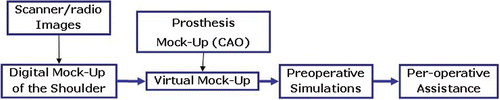
Figure 2. Computer-aided surgery system for placement of shoulder prosthesis.
This paper is organized in three parts: the next section reviews the state of the art in various areas of computer assisted surgery (CAS); a proposed CAS procedure for shoulder replacement is then presented; and the article ends with conclusions and discussion of future work.
State of the art
The purpose of the virtual object in each CAS application is to provide a realistic representation of the bony structures or organs that are involved in the intervention. Acquisition of virtual objects (VOs) may be achieved either preoperatively or intraoperatively. Approximately a decade ago, the first computer assisted orthopaedic surgery (CAOS) systems were introduced based on preoperatively acquired CT scans. The advantage of such a system is that it offers excellent contrast between bone and soft tissue. Moreover, the acquired images are geometrically undistorted and thus no sophisticated calibration is required. These advantages make CT images superior to MRI as preoperative VOs, although the latter method has clear advantages in terms of the patient's radiation exposure. Some efforts have been made to overcome MRI-related difficulties Citation[3],Citation[4], but CT remains the method of choice for preoperative imaging for CAOS applications.
Another drawback of preoperative VOs led to the introduction of intraoperative imaging modalities. The bony morphology may change between image acquisition and performance of the actual surgical procedure. Consequently, the VO may not necessarily correspond to the therapeutic object, leading to unpredictable inaccuracies during navigation or robotic procedures. This effect can be particularly problematic for traumatology in the presence of unstable fractures. To overcome this difficulty, the use of intraoperative CT scanning has been proposed Citation[5], but the infrastructural changes required for implementation of this approach are tremendous, often involving considerable reconstruction of a hospital's facilities Citation[6]. An alternative approach is the use of established intraoperative imaging modalities. Several research groups have developed navigation systems based on fluoroscopic images Citation[7],Citation[8]. The fluoroscope is a well-established device in orthopaedic and trauma treatment, and could therefore be integrated into CAOS systems more easily than intraoperative CT. In contrast to CT, however, images generated with a fluoroscope are usually distorted due to a number of factors. To use fluoroscopic images as VOs therefore requires calibration of the fluoroscope, which involves the attachment of marker grids to the image intensifier and the tracking of its position and orientation with the navigator during image acquisition Citation[7],Citation[8]. The resulting real-time visual feedback provided by the navigation system is similar to the use of the fluoroscope in constant mode. This technique is therefore also known as “virtual fluoroscopy” Citation[9]. Although only 2D projections are available and the images usually lack contrast when compared to preoperative CT, the advantages of fluoroscopy-based navigation preponderate for a number of clinical applications.
Recently, a novel imaging device has been developed Citation[10] that enables the intraoperative generation of 3D fluoroscopic image data. It consists of a motorized, isocentric C-arm that acquires series of 50–100 2D projections and from them reconstructs 13 × 13 × 13 cm volumetric datasets that are comparable to CT scans. Initially advocated primarily for surgery on the extremities, this “fluoro-CT” has been adopted for use with a navigation system and has already been applied to several anatomic areas (see Clinical fields of application below). One major advantage of the device is that it combines the availability of 3D imaging with intraoperative data acquisition.
A final category of navigation systems functions without using any radiological images as VOs. Instead, the tracking capabilities of the system are used to acquire a graphic representation of the patient's anatomy by intraoperative digitization. Using any tracked instrument, the spatial location of anatomic landmarks can be recorded. Combining the obtained points into lines and surfaces will generate, step by step, an abstract model of the geometry. As this model is generated by the operator, the procedure is known as “surgeon-defined anatomy” (SDA). The technique is particularly useful when soft tissue structures such as ligaments or cartilage boundaries are to be considered that are difficult to identify on CT or fluoroscopic images. Moreover, some locations can be acquired without direct access by a digitizing instrument. For instance, the center of the femoral head, which is an important landmark during total knee replacement, can be reconstructed from recorded passive rotation of the leg around the acetabulum. However, the generated images are often rather abstract and not easy to interpret. Sati et al. Citation[11] suggested underlaying a preoperative X-ray to facilitate orientation, but precise matching of the two image spaces turned out to be difficult.
An alternative concept is provided by the so-called bone morphing technique Citation[12],Citation[13]. This process uses a database of generic 3D statistical computer models of bones and a set of specific points that are acquired with the SDA technique. Analyzing the recorded data enables the system to select the bone model from the data pool that best matches the patient's morphology. A special morphing algorithm then deforms the selected model three-dimensionally until it fits the acquired points as perfectly as possible. As a result, a realistic virtual model of the structure to be operated on can be presented and used as a VO without any conventional image acquisition.
In our work, we started with the idea that CT scans are not always available, so our shoulder model can be parameterized using X-rays or CT. For the application, it is not necessary to perform accurate modeling of a real shoulder joint: a model based on simple forms is sufficient for measuring the prosthetized shoulder.
Proposed method
Shoulder anatomy
The shoulder is the most mobile joint in the body, but this great mobility has a corollary: a high degree of instability that is responsible for most of the mechanical pathologies encountered. The joint is composed of the humeral head and the articular cavity of the scapula or glenoid, covered by the articular cartilage. The scapula extends to form the bony excrescence: the acromion surrounds the shoulder from back to front to form its roof, and the coracoid process is anterior of this (see ). The stability of the gleno-humeral joint is assured by the rotator cuff muscle.
Figure 3. The bony part of the shoulder with the rotator cuff at left. [Color version available online.]
![Figure 3. The bony part of the shoulder with the rotator cuff at left. [Color version available online.]](/cms/asset/0c5de4fe-ef87-4098-8571-f4ec9576ab7d/icsu_a_221003_f0003_b.gif)
The great mobility of the shoulder arises from a combination of the amplitude of the gleno-humeral joint and the mobility of the scapulo-thoracic joint (). Due to the presence of the trunk, adduction is impossible unless combined with retropulsion or antepulsion. During the clinical examination of abduction mobility, the difference between the gleno-humeral joint mobility and the scapulo-humeral mobility should be assessed. It is necessary to fix the scapula in place with one hand and note the abduction position from which the scapula is pulled by the arm (see ).
Figure 4. (a) Antepulsion and retropulsion movement. (b) Adduction movement. [Color version available online.]
![Figure 4. (a) Antepulsion and retropulsion movement. (b) Adduction movement. [Color version available online.]](/cms/asset/f5f02348-bd74-4808-b9b6-8eaab2ffcfb5/icsu_a_221003_f0004_b.gif)
Table I. Movement of shoulder.
Digital mock-up
Comparison of different techniques for modeling the shoulder
With respect to the final application (CAS), different criteria are required to determine the best possible modeling method:
A parameterizable surface, which allows the parameters to be changed so as to adapt the surface to the morphological characteristics of the patient;
Parameter type, because a surface ruled by physical parameters consents to deform the model morphologically, which is not the case with mathematical parameters;
Logical operators, because the surface has to facilitate logical operations to ease the subsequent virtual surgery.
Table II. Comparison of methods.
Radial basis function (RBF), Kohonen maps, and simple-form modeling methods are parametric representations. Nevertheless, for RBF () and Kohonen maps, the parameters are purely mathematical and do not represent any anatomical information (such as the diameter of the humeral head or the length of the humerus). Moreover, it seems quite difficult to determine anatomical information by combining the mathematical parameters of these representations. All the other methods are non-parametric, so that the shape and size of the reconstruction can hardly be adapted to the patient morphology unless a morphing algorithm is applied.
Figure 5. Radial basis function (RBF) reconstruction and deformations. The original reconstruction is at the center of the figure. [Color version available online.]
![Figure 5. Radial basis function (RBF) reconstruction and deformations. The original reconstruction is at the center of the figure. [Color version available online.]](/cms/asset/58382d10-cc83-4a37-9bf2-5549403c5f01/icsu_a_221003_f0005_b.gif)
Proposed model
The chosen modeling method is the simple-form approach. In this method, the bones of the shoulder are represented by quadrics and boxes (sphere, cylinder, etc.) that can be handled with a very few parameters. As already stated, the data provided by the surgeon are sufficient to parameterize this kind of model (see next section). Furthermore, logical operations such as subtraction or intersections can easily be computed on quadrics and boxes so that the drilling and cutting operations can be simulated on the model and a virtual operation can be performed easily ().
Figure 6. The shoulder joint and the developed simple-form model. [Color version available online.]
![Figure 6. The shoulder joint and the developed simple-form model. [Color version available online.]](/cms/asset/6f91512d-c526-4f1a-b1bd-b99cfe18ab52/icsu_a_221003_f0006_b.gif)
It is important to note that the model is used in the context of the prosthetic replacement of the joint. In our case, the inverse DUOCENTRIC® prosthesis is to be installed, and for that application it is not necessary to accurately model a real shoulder joint. Only certain parts of the model need be accurately reconstructed: particularly those parts where the prosthesis will be fixed. shows that the simple-form model is sufficient for this application, with an average error of 3 mm between a simple-form humeral model and a reconstructed bone, and of 0.1 mm between a simple-form scapula model and a reconstruction. For these experiments, a real bone was scanned with a laser-based triangulation scanner; the simple-form model and the scanned model were then registered and the error estimated.
Figure 7. Measurement of error between reality and the simple model. [Color version available online.]
![Figure 7. Measurement of error between reality and the simple model. [Color version available online.]](/cms/asset/291055ba-2102-4e47-8c70-07d276953be1/icsu_a_221003_f0007_b.gif)
The simple-form model is composed of quadrics, boxes, and also Dupin supercyclides Citation[23] to link the different forms. For instance, the humerus is mainly composed of a sphere and a cylinder Citation[24]. A Dupin cyclid is added to ensure the continuity and completeness of the model, and the bicipital groove is modeled by carving a cylinder into the humeral head. The scapula is composed of planes, ellipsoids, cylinders and so on. This way, only 14 parameters are necessary to compute a model adapted to the morphology of the patient. The parameters of interest described in were selected in accordance with the recommendations of orthopaedic specialists Citation[25–27]. The link between relevant parameters and simple-form parameters that validates our choice will be stated in the next sub-section.
Table III. Parameters of the simple-form model.
Extraction of parameters of the simple-form model
Due to the lack of data (CT slices not always being available), the reconstruction of an individual model for each patient is not feasible. Moreover, deformation or morphing of a generic model may require the measurement of many 3D control points on the patient's shoulder, which could be a drawback. Therefore, in collaboration with orthopaedic specialists, we decided to model the scapulo-humeral joint using simple geometric forms that allow a parametric model to be obtained from a minimal set of data extracted from medical images, and that permit the main characteristics involved in shoulder mobility to be considered.
The goal is to provide a full system for extracting parameters of the chosen model in a simple manner from patient morphology. More precisely, the system should be able to extract parameters from radiological images. To that end, a procedure has been established by the surgeons to generate useful radiological images. To validate the method of extraction, a system has been developed to extract parameters from scanner images.
The proposed approach consists of automatic (or sometimes supervised) extraction of relevant parameters from various medical images (CT slices, X-ray images, etc.). Good-quality CT slices are necessary for success; a high contrast is required to detect the scapula and humerus. The CT images must also have a readable and precise scale to permit computation of the coefficient conversion from pixels to centimeters. In the automatic extraction, the parameters of the scapula or humerus bones are extracted from the images without operator intervention. However, it is still important to select good images from which to extract the desired measurement (this is also true for supervised extraction). When all the parameters have been extracted, the construction of the model can commence. We have developed an ergonomic software that permits easy extraction of the different parameters, even by a non-specialist in image processing. A screenshot of this software is shown in .
Figure 8. Automatic and supervised extraction of the humeral head radius. [Color version available online.]
![Figure 8. Automatic and supervised extraction of the humeral head radius. [Color version available online.]](/cms/asset/02ea4136-4a3d-4104-8453-a9c70cadd51d/icsu_a_221003_f0008_b.gif)
Before measuring the parameters, the CT slices are pre-processed. The images are composed of primary colors (RGB), and an algorithm enables transformation of these slices into binary images in order to extract the desired measurements. To illustrate this, the process for extracting the radius of the humeral head is as follows:
Extraction of luminance. The colored image is converted from RGB space to HSL space. We extract the plane that gives the best contrast for the majority of slices. In output, we obtain a gray-level image.
Thresholding. This step is very important, and success essentially depends on the contrast of the image. Images with low contrast are the most difficult to exploit. In this case, there is a process for improving the gray-level distribution: histogram equalization gives reasonably good results. The resulting histogram is monomodal, with the darkness peak corresponding to the tissue (around 50 in the example given). The bones appear a little more clearly in the image; a threshold was chosen at the end of the peak (70 in this example).
Mathematical morphology operations. Two mathematical operations are necessary to isolate the areas of interest in the image: particle filtering and hole-filling. The first operation permits cancellation of noise and artefacts in the thresholded image by removing all the particles having an area less than that of the structuring element employed. This allows deletion of the portions of the extracted area that do not represent bones. The second operation permits all the holes to be filled. Finally, a particle filter is applied to select the bone that is to be extracted (in this case, the humerus) Citation[28]. illustrates the whole sequence of image processing from the original CT scan to the segmented humeral head area.
Figure 9. Image processing method for the extraction of the diameter of the humeral head. [Color version available online.]
![Figure 9. Image processing method for the extraction of the diameter of the humeral head. [Color version available online.]](/cms/asset/8477921c-62f1-4246-ab4c-dbd184f19053/icsu_a_221003_f0009_b.gif)
Integration of the prosthesis into the model
The DUOCENTRIC® inverse prosthesis is indicated when the muscles which stabilize the shoulder joint (the rotator cuff) have been cut and only the deltoid muscle is functional. The computer assisted design (CAD) model of the prosthesis is integrated into the shoulder simple-form model as illustrated in . The surgeon can choose the prosthesis with different sizes of components.
Figure 10. Digital mock-up of the shoulder joint with integration of the prosthesis. [Color version available online.]
![Figure 10. Digital mock-up of the shoulder joint with integration of the prosthesis. [Color version available online.]](/cms/asset/2875b240-b771-4333-b2ac-ebc5fffdf867/icsu_a_221003_f0010_b.gif)
Preoperative simulation
The digital mock-up of the shoulder joint with the CAD model of the prosthesis is used to simulate the surgical procedure. A collision-detection algorithm to detect collisions between the prosthesis and the bones is added to measure the mobility of the joint with respect to the position of the prosthesis and the patient morphology. The optimal positioning of the prosthesis can also be deduced from this. Logical operations such as subtraction or intersection can be easily computed using this simple model, so that drilling and cutting operations can be simulated on the model and a virtual operation considered with real-time performance in a PC calculator ().
Figure 11. Simulation of movement of the prosthesized shoulder after cutting the humeral head. [Color version available online.]
![Figure 11. Simulation of movement of the prosthesized shoulder after cutting the humeral head. [Color version available online.]](/cms/asset/49b0cd9d-8553-4527-9784-8d97cde1a472/icsu_a_221003_f0011_b.gif)
According to the placement of the prosthesis in the bones, the movements of the prosthetic joint can be simulated as shown in for abduction and adduction movements. The simulation of both movements helps the surgeon to optimize the rotation torque of the arm. With reference to the relative position of the prosthesis in the bones, the surgeon can verify the mobility and the feasibility of his proposed operation.
Figure 12. Results for mobility according to the choice of cutting plane. [Color version available online.]
![Figure 12. Results for mobility according to the choice of cutting plane. [Color version available online.]](/cms/asset/aab9b737-c745-4876-a71e-74a2d9eb8956/icsu_a_221003_f0012_b.gif)
presents two results that can be obtained when the cutting plane is moved. For abduction, we obtained a value of 77° for the first position of the plane and 88° for the second position, which is quite close to the average value of 70° obtained on non-pathological shoulders. For adduction, the two values obtained were 19° and 13°; the average non-pathological value is 30°. This discrepancy can be explained by the fact that adduction is computed in isolation and is not combined with antepulsion or retropulsion. Moreover, the trunk is not modeled at all, which leads to erroneous results. In our future work, the trunk will be modeled as an obstacle.
Note that the position of the support of the glenoid can also be changed to obtain other mobility results. Hence, the surgeon can test the best position of the prosthesis, propose different scenarios, and save them for use in real time during the operation.
Conclusion and future work
A guided tool for the planning of prosthetic surgery has been presented. Our goal was to develop a shoulder model specifically designed for application in the prosthetic replacement of the shoulder joint. This model, validated by a surgeon, was based on the use of simple forms; unnecessary details of the joint, which are strongly dependant on the patient, are not represented. The model is adaptable for each patient using parameters that can be extracted from CT images or radiological images. The use of only radiological images is of particular interest. The model is very light and can be manipulated very easily. Virtual surgery can be performed interactively.
As a future project, the 3D model and virtual surgery system will be integrated into a real-time augmented reality device which will be constituted from the spatial positioning of the patient (bones) and surgeon (tools), the registration of the simple model and the real bones of the patient, and the development of an ergonomic control interface ().
Figure 13. Augmented virtuality system. [Color version available online.]
![Figure 13. Augmented virtuality system. [Color version available online.]](/cms/asset/bf13a5df-cdf6-4191-9d25-17d9cae65c2c/icsu_a_221003_f0013_b.gif)
References
- Cavaille A. Résultat d’une prothèse d’épaule compatible avec une destruction totale de la coiffe des rotateurs. University of Burgundy, France 1993, PhD thesis
- Couteau B, Mansat P, Darmana R, Mansat M, Egan J. Morphological and mechanical analysis of the glenoid by 3D geometric reconstruction using computer tomography. Clinical Biomechanics 2000; 15(1)8–12
- Martel AL, Heid O, Slomczykowski M, Kerslake R, Nolte LP. Assessment of 3-dimensional magnetic resonance imaging fast low angle shot images for computer assisted spinal surgery. Comput Aided Surg 1998; 3: 40–44
- Suhm N, Simeria A, Hügli R, (2003) MR-imaging of bone cements as a first step towards MR-guided vertebroplasty. Proceedings of the Third Annual Meeting of the International Society for Computer Assisted Orthopaedic Surgery (CAOS-International), MarbellaSpain, June, 2003, F Langlotz, BL Davies, A Bauer, et al. Steinkopff, Darmstadt, 356–357
- Jacob AL, Messmer P, Kaim A, Suhm N, Regazzoni P, Baumann B. A whole-body registration free navigation system for image-guided surgery and interventional radiology. Invest Radiol 2000; 35: 279–288
- Messmer P, Jacob AL, Fries E, et al. Technologieintegration und Prozessmanagement – Konzept und Implementierung einer neuartigen Plattform für einzeitige Diagnostik und Therapie des akut Kranken und Verletzten sowie für elektive computerassistierte Chirurgie (CAS). Unfallchirurg 2001; 104: 1025–1030
- Hofstetter R, Slomczykowski M, Bourquin Y, Nolte LP (1997) Fluoroscopy based surgical navigation -- concept and clinical applications. Computer Assisted Radiology and Surgery. Proceedings of the 11th International Symposium and Exhibition (CAR’97), BerlinGermany, June, 1997, HU Lemke, MW Vannier, K Inamura. Elsevier, Amsterdam, 956–960
- Joskowicz L, Milgrom C, Simkin A, Tockus L, Yaniv Z. FRACAS: A system for computer-aided image-guided long bone fracture surgery. Comput Aided Surg 1998; 3(6)271–288
- Foley KT, Simon DA, Rampersaud YR. Virtual fluoroscopy: Computer-assisted fluoroscopic navigation. Spine 2001; 26: 347–351
- Heiland M, Schulze D, Adam G, Schmelzle R. 3D-imaging of the facial skeleton with an isocentric mobile C-arm system (Siremobil Iso-C3D). Dentomaxillofac Radiol 2003; 321: 21–25
- Sati M, Stäubli HU, Bourquin Y, Kunz M, Nolte LP. Real-time computerized in situ guidance system for ACL graft placement. Comput Aided Surg 2002; 7: 25–40
- Fleute M, Lavallée S, Julliard R. Incorporating a statistically based shape model into a system for computer assisted anterior cruciate ligament surgery. Med Imaging Anal 1999; 3: 209–222
- Stindel E, Briard JL, Merloz P, Plaweski S, Dubrana F, Lefevre C, Troccaz J. Bone morphing: 3D morphological data for total knee arthroplasty. Comput Aided Surg 2002; 7: 156–168
- Boudjemaï F, Enberg PB, Postaire JG. Surface modeling by using self organizing maps of Kohonen. Proceedings of the 54th IEEE International Conference on Systems, Man and Cybernetics (SMC’03), Washington, DC, October, 2003. 3: 2418–2423
- Ferley E, Cani-Gascuel MP, Attali D. Skeletal reconstruction of branching shapes. Proceedings of the 2nd International Workshop on Implicit Surfaces, EindhovenThe Netherlands, October, 1996, 127–142
- Kohonen T. Self-organized formation of topologically correct feature maps. Biological Cybernetics 1982; 43: 59–69
- Lanquetin S. Etude des surfaces de subdivision: Intersection, précision et profondeur de subdivision. University of Burgundy, France 2004, PhD thesis
- Lorensen WE, Cline HE. Marching Cubes: A high resolution 3D construction algorithm. Proceedings of 14th Annual Conference on Computer Graphics and Interactive Techniques (SIGGRAPH 1987), Computer Graphics 1987;21(4):163–169
- Muraki S. Volumetric shape description of range data using blobby model. Proceedings of 18th Annual Conference on Computer Graphics and Interactive Techniques (SIGGRAPH 1991), Computer Graphics 1991;25(4):227–235
- Pontier S. Reconstruction d’objets déformables à l’aide de fonctions implicites. University of Lyon I, France 2000, PhD thesis
- Tafihery RA. 3D object modeling using radial basis function. Research Report. LausanneSwitzerland, 2003. EPFL
- Bittar E, Tsingos N, Gascuel M. Automatic reconstruction of unstructured 3D data: Combining a medial axis and implicit surfaces. Proceedings of EUROGRAPHICS 1995, MaastrichtThe Netherlands, September, 1995, 457–468
- Foufou S, Garnier L. Implicit equations of supercyclides. Proceedings of the International Conference on Advances in Constructive Approximation, Nashville, May, 2003, 14–17
- Boileau P, Walch G. The three-dimensional geometry of the proximal humerus. J Bone Joint Surg 1997; 79: 857–865
- Atmani H, Mérienne F, Fofi D, Trouilloud P. Constructing a simple parametric model of shoulder from medical images. Proceedings of SPIE Electronic Imaging -- Machine Vision Applications in Industrial Inspection XIV, San José, CA, January, 2006
- Atmani H, Mérienne F, Fofi D, Trouilloud P. Towards a computer-aided surgery system for shoulder prosthesis placement. Presentation at 14th Annual Medicine Meets Virtual Reality Conference (MMVR14), Long Beach, CA, January, 2006
- Atmani H, Fofi D, Mérienne F, Trouilloud P. Virtual mock-up of shoulder articulation for an aided surgery system. Proceedings of 2nd Workshop on Computer Assisted Diagnosis and Surgery, Santiago de Chile, March, 2006, 1–5
- Serra JP. Image Analysis and Mathematical Morphology Volume 1. Academic Press, San Diego 1988; 70–89