Abstract
Objective: Replacement of the diseased shoulder joint with implants is a procedure whose frequency is rapidly increasing. However, glenoid replacement remains challenging due to the difficult joint exposure and visualization of anatomical reference landmarks during the procedure. Improper positioning of the glenoid component can lead to early failure. The objective of this study was to develop and evaluate a Computer Assisted Glenoid Implantation (CAGI) technique to achieve a more accurate and reliable placement of the glenoid component.
Materials and Methods: Twenty cadaveric scapulae were imaged with CT. The accuracy of an electromagnetic tracking system and 3D surface modeling for the measurement of glenoid position was compared to that of the standard CT-based method. Custom jigs were then developed to track instruments and to correct for scapular motion during in vitro trials. A standardized protocol for determining, in real time, the glenoid position and placement was developed and validated.
Results: The version angles measured by the tracking system, CT, and the 3D modeling software were 0.0 ± 1.2°, -1.3 ± 1.0°, and -1.1 ± 1.1°, respectively. The magnitudes for inclination angles were 0.7 ± 0.7°, 0.9 ± 0.8°, and 1.0 ± 0.7°, respectively. A statistically significant difference was found only between measurements made with the tracking system and with CT (p < 0.05). Testing of the CAGI system in a cadaveric trial resulted in an accuracy of 1.17° of version and 0.60° of inclination. The procedure was readily performed with excellent feedback and guidance for the surgeon.
Conclusions: Preoperative planning using CT imaging with 3D modeling and intraoperative tracking were combined to produce improved accuracy and reliability of glenoid implantation in the setting of total shoulder arthroplasty.
Introduction
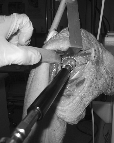
Replacement of the diseased shoulder joint with implants is a procedure whose frequency is rapidly increasing. However, replacement of the glenoid component remains the weak link in total shoulder arthroplasty and is a common cause of revision surgery Citation[1]. Positioning of the glenoid component is challenging due to the difficult surgical exposure and intra-operative visualization (), as well as the lack of accessible anatomical reference landmarks Citation[2]. Other challenges include the poor bone stock and the high variability in orientation secondary to eccentric wear from arthritis. Improper positioning and orientation of the glenoid component can lead to fractures, loosening, early wear, and instability. Unlike the hip, the smaller size of the glenoid allows only a narrow margin of error.
Figure 1. Intraoperative view of the shoulder during reaming of the joint surface. Visualization of the glenoid face and orientation is difficult during reaming and drilling without computer assisted navigation.
It is logical to postulate that employment of computer assisted techniques would result in improved surgical outcomes. This could be achieved via preoperative imaging and/or intraoperative digitization and scanning to quantify the native structure. Using appropriate intraoperative guidance and tracking technology, the implant could then be positioned at the target location, thereby minimizing error.
In view of the above, the objective of this study was to design and develop an intraoperative tracking system for glenoid implantation. We hypothesized that a Computer Assisted Glenoid Implantation (CAGI) technique could be developed to produce more accurate and reliable placement of the glenoid component. Our specific aim was to develop the CAGI technique to optimize placement of the glenoid component with respect to two anatomical angles: Version and inclination.
Materials and methods
Definition of glenoid position and anatomical locations
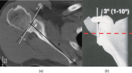
Glenoid version is defined as the axial tilt of the glenoid face and is measured on a CT scan as the angle formed between the transverse axis of the scapula and the glenoid face . Anterior tilting represents positive version (anteversion) and posterior tilting represents negative version (retroversion) Citation[3]. Glenoid inclination is defined as the vertical orientation of the glenoid and represents the angle formed between the transverse axis of the scapula and a line through the glenoid face . Superior tilting represents positive inclination and inferior tilting represents negative inclination Citation[1].
The superior point is defined as a point on the superior glenoid rim at the junction of the coracoid and the glenoid face . The inferior point is defined as the junction of the inferior glenoid rim and an imaginary line extending from the lateral scapular body. This is palpable intraoperatively as the surgeon palpates the body of the scapula immediately inferior and medial to the glenoid. The midpoint between the anterior edge and posterior edge of the lateral body of the scapula is used to draw that imaginary line. A line drawn between the superior and inferior points was defined as the vertical axis.
Figure 3. Selection of anatomical landmarks on the scapula: (a) superior, inferior, anterior, and posterior points; (b) medial point; (c) transverse axis.
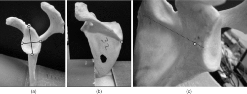
The anterior point was defined as a point on the anterior glenoid rim at the junction of the glenoid face and the extrapolation of a line along the neck of scapula. This represents the transverse axis of the scapula, which is used as the reference axis to measure glenoid version and inclination .
The posterior point was defined as a point on the posterior glenoid rim at the junction of the glenoid face with a line perpendicular to the vertical axis . A medial angle point was defined as a point on the medial border of the scapula, in the same horizontal plane as the medial edge of the scapular spine .
Analytical techniques
Digitization and measurement of version and inclination were performed on CT images and on 3D images reconstructed (Mimics, Materialise, Ann Arbor, MI) and processed in a surface modeling software (Rhinoceros, Robert McNeel & Associates, Seattle, WA). Thresholding was done manually on an individual specimen basis, based on the operator's experience. Contours for each scapula were generated in the CT slice plane and exported into the computer modeling software (Rhinoceros) via an IGES format.
Key anatomical landmarks were identified by the surgeon on the contours using multiple planar views to navigate the virtual environment. The superior, inferior, anterior, and posterior points on the glenoid rim, as well as a medial angle point on the medial aspect of the scapula, were identified. These points were determined in a manner similar to that in which they would be found in a physical specimen, as described below.
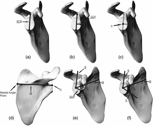
Algorithms were prepared in Rhinoceros to measure version and inclination relative to an anatomical coordinate system. The anatomical scapular coordinate system was created as follows (and as detailed in ):
A line between the superior and inferior points was created, labeled Sup.
A line perpendicular to Sup passing through the anterior point was created, labeled Ant.
The point on the glenoid surface closest to the intersection of Ant and Sup defined the center of the coordinate system, C.
The medial axis was defined using a vector joining C and the medial angle point, labeled M.
The superior direction was defined by the cross product of M and Ant, labeled S.
Anterior was defined as the cross product of M with S, labeled A.
Development and validation of a measurement technique
A standardized protocol for determining, in real time, the glenoid center, version, inclination and final glenoid component placement was developed and validated to determine the feasibility of tracking surgical instruments.
Twenty cadaveric scapulae were scanned with CT slices 0.625 mm thick (GE Lightspeed Ultra CT scanner). The accuracy and reliability of an electromagnetic tracking system (Flock of Birds, Ascension Technologies, Burlington, VT) and a 3D surface modeling software (Rhinoceros) for the measurement of glenoid orientation were compared to those of the standard CT-based method Citation[7]. The tracking system has been well validated in our laboratory and has positional and angular accuracy of 0.8 mm and 0.5°, respectively Citation[4].
The scapulae were mounted using a 316L stainless steel clamp affixed to a testing base that did not affect the tracking system Citation[5]. Key anatomical points on the scapulae were digitized with an electromagnetic stylus pointer.
In order to have navigational targets according to the preoperative plan, the clinical measurements that were made in Mimics and Rhinoceros had to be transformed to the specimen anatomy intraoperatively. This was achieved with a paired-points registration using three points on the glenoid face (superior, inferior and anterior points) that were selected as described above. These points were selected on the 3D models generated from the CT data during the pre-operative planning stage. Then, the same points were digitized on the specimen anatomy following intraoperative glenoid exposure. The posterior point was not used in the registration because it is often not available due to arthritic wear or other pathology Citation[6–8]. From these three points, a coordinate system was created, resulting in the transformation matrix needed for the registration. This coordinate system was used only for registration and was then discarded. Thus, it was dubbed the intermediate coordinate system.
The final coordinate system used to calculate clinical angles for navigational feedback was also transformed to the anatomy during the registration. This coordinate system was generated from points selected in the preoperative planning stage.
Registration and intraoperative tracking were performed with custom written code using LabVIEW 7.1 (National Instruments, Austin, TX). shows the real-time interface that the surgeon uses to track the position of the reamer with respect to the glenoid face. This graphical interface relayed implant position relative to the planned position, thereby guiding the surgeon in placing the implant according to the preoperative CT measurements.
Figure 5. The computerized output showing the CAGI interface. In this screen view, the position of the reamer with respect to the glenoid face is shown. The left image represents an anterior view of the glenoid and the right image represents a superior view of the glenoid. The surgeon aligns the crossing axes, which represent the line of trajectory of the reamer, with the crossing axes of the target. (SUP = superior; INF = inferior, POST = posterior; ANT = anterior; MED = medial; LAT = lateral.) [Color version available online.]
![Figure 5. The computerized output showing the CAGI interface. In this screen view, the position of the reamer with respect to the glenoid face is shown. The left image represents an anterior view of the glenoid and the right image represents a superior view of the glenoid. The surgeon aligns the crossing axes, which represent the line of trajectory of the reamer, with the crossing axes of the target. (SUP = superior; INF = inferior, POST = posterior; ANT = anterior; MED = medial; LAT = lateral.) [Color version available online.]](/cms/asset/f09ef3fd-2aed-45e1-922d-565141624861/icsu_a_237321_f0005_b.gif)
Development of mechanical/tracking instrumentation
Standard surgical instruments were augmented with electromagnetic trackers in order to achieve 3D computer navigation and feedback of clinical angles (). Using standard instruments for the computer-navigated phase allowed comparison of the traditional and computer assisted techniques without influence from the instruments.
Figure 6. The instrumentation developed to track both drilling and reaming of the glenoid surface. Electromagnetic trackers were mounted on the drill guide (a) and pneumatic reamer (b) via custom fabricated Delrin® mounts at a compatible distance.
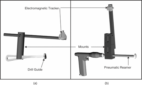
The electromagnetic trackers are susceptible to errors induced by metallic interference from the surgical instruments Citation[5]. For this reason, the tracker mounts were designed as outriggers to maintain the trackers at a compatible distance from the instruments. Two mounts were machined from Delrin®: one for the drill guide; the other for the pneumatic reamer. The position and orientation feedback of the tracked instruments was tested and verified to ensure that they produced no undue errors compared to the tracker manufacturer's specifications.
Validation of the CAGI procedure
A trial of this system was conducted using paired cadaver shoulders. The procedure was conducted by an experienced shoulder surgeon (K.J.F). A standard deltopectoral approach was used to access the glenohumeral joint. The humeral head was resected and the glenoid exposed according to standard surgical techniques of total shoulder arthroplasty. Version and inclination were measured from the glenoid using the same anatomical points that were digitized via electromagnetic tracking. Registration was then performed to align the image-derived coordinate system to the specimen's anatomical coordinate system. This allowed for preoperative planning of the final position of the glenoid component ().
Figure 7. Final positions for the glenoid component in the preoperative plan along the inferior (a) and lateral (b) edges of the glenoid. [Color version available online.]
![Figure 7. Final positions for the glenoid component in the preoperative plan along the inferior (a) and lateral (b) edges of the glenoid. [Color version available online.]](/cms/asset/2e4cace3-e2f2-44ea-ac29-5c8fd0b4e88e/icsu_a_237321_f0007_b.gif)
A calibration was performed at the start of this experimental trial to assess the accuracy and safety of the tracking system by aligning the instruments along the orientation of the native glenoid face prior to reaming. The location of the glenoid center and the orientation of the glenoid, as recorded by the tracked instruments, were compared with the angles measured on the CT scans.
The surgical goal was to implant the glenoid component in the center of the glenoid at 0° version and 5° inclination, which represents the ideal orientation of the glenoid in the setting of total shoulder arthroplasty.
Results
Validation of the measurement techniques
The version angles measured by the tracking system, CT, and the 3D modeling software were 0.0 ± 1.2°, -1.3 ± 1.0°, and -1.1 ± 1.1°, respectively. The magnitudes for inclination angles were 0.7 ± 0.7°, 0.9 ± 0.8°, and 1.0 ± 0.7°, respectively. A statistically significant difference (mean = 1.3°) was found only between measurements made with the tracking system and with CT (Repeated Measures ANOVA p < 0.05).
Accuracy of the CAGI procedure
The accuracy results for the cadaveric trial were quantified by taking the achieved values and subtracting from the goal (0° version, +5° [superior] inclination). These were based on the post-CT measurements. Results for the CAGI trial were 1.17° of version and 0.60° of inclination; results from the traditional side were 11.47° of version and 3.48° of inclination. Results for post drilling, as measured via the tracking system, were 0.1° of version and 1.2° of inclination for the CAGI trial, and 10.7° of version and 5.6° of inclination for the traditional trial. It was also noted that the procedure was readily performed with excellent feedback and guidance for the surgeon. Moreover, the operative time was not notably different between the two groups.
Discussion
A number of surgeons choose to perform only hemiarthroplasty of the shoulder rather than total shoulder arthroplasty because of challenges associated with adequate glenoid exposure. However, a recent meta-analysis has shown that patients with total shoulder arthroplasty achieve greater pain relief and have greater satisfaction and overall function than patients treated with hemiarthroplasty Citation[9]. It is possible that surgical methods employing techniques reported in this paper will improve the surgeon's ability to reliably resurface the glenoid.
Computer assisted surgical techniques have become popular for hip and knee arthroplasty, but similar developments for the shoulder are still in their infancy Citation[10–15]. There is currently no established computer assisted method for shoulder replacement that has been fully developed for the accurate placement of the glenoid component based on preoperative images. Surgeons rely on preoperative templating of radiographs, intraoperative instrumentation that accompanies the implant system, and their own experience. Current instruments for measuring version are not sufficiently accurate and only estimate the correction needed for version based on the CT measurement, which may be incorrect.
Current preoperative CT measurement techniques for glenoid orientation Citation[3] are subject to rotational errors due to non-standardized patient positioning techniques during image acquisition Citation[16]. These unaccounted changes in rotation or inclination of the scapula can change the measured version on the chosen CT axial slice Citation[16]. The unknown scapular orientation during CT makes it difficult to obtain an accurate version measurement on the chosen CT axial slice, which can lead to improper intraoperative placement of the glenoid component. The CT-based measurement approaches that we have described may make this procedure less difficult.
With respect to the comparison of measurement techniques, we did find a significant difference between the tracking system results and CT-based measurements. However, these results were very close, within 1°, and the differences are unlikely to be clinically significant.
A standardized protocol for real-time determination of the glenoid center, version, inclination and final glenoid component placement was developed and validated in this study. Preoperative planning using CT imaging with 3D modeling and intraoperative tracking were combined to produce improved accuracy and reliability of glenoid implantation in the setting of total shoulder arthroplasty.
Glenoid replacement using the traditional method is technically challenging. Current surgical instrumentation used for glenoid preparation is poorly fitted on the glenoid face, and is subject to inaccuracies inherent to the instrument designs. Visualization is obscured during reaming by the reamer heads (), and the surgeon must estimate the native version, the correction needed, and the final version achieved without an accurate sense of the scapula orientation. The largest errors in version were observed during drilling and reaming. Care should be taken during the critical reaming step because errors in reaming are perpetuated into the drilling phase, affecting the final version of the glenoid component.
Preoperative planning, 3D CT modeling and intraoperative tracking (using the CAGI approach) produced improved accuracy of glenoid implantation. The error of the system was less than 1.5°. Hence, CAGI appears to offer a significantly more accurate measurement of glenoid orientation than the traditional empirical method Citation[3]. CAGI also allows for preoperative templating of the final position of the glenoid component, and can help the surgeon decide on the optimal orientation of the implant. This standardized protocol removes the user variability involved in estimating scapular rotation, which affects the measurement of the true glenoid version Citation[16]. This error could potentially be reduced by the use of more precise instruments, better registration and calibration techniques. Certainly, with CAGI the target zone was smaller than for the traditional group, and CAGI could prevent the occurrence of outliers. A further study examining a larger series of specimens is needed to more fully determine the accuracy of the CAGI method.
Limitations of the CAGI system consisted of the system error from the tracking system, the instruments and the calibration. Also, the cost of the system must be weighed against the ultimate cost of revision surgery. Lastly, the extra time spent in the planning as well as the execution of CAGI must be weighed against improved functional outcomes and decreased revision rates.
It should also be noted that the experiments proposed in this study represent somewhat of a best-case scenario. The difference in errors obtained might have been larger had the procedure been performed by a less experienced surgeon. CAGI may help surgeons who perform total shoulder arthroplasty on a less regular basis, while serving as an invaluable training tool for residents and fellows.
The results obtained from this in vitro study suggest that CAGI is efficacious in a laboratory environment and warrants further study. CAGI should improve prosthetic longevity and decrease revision rate in the clinical setting. The potential of incorporating this image-based method to achieve proper reconstruction of other joints in orthopaedics and also to improve solid organ surgical procedures in other specialties is considerable.
Acknowledgments
We would like to thank the Natural Sciences and Engineering Research Council - Collaborative Health Research Partnerships for the research grant. The assistance of Angela Kedgley, Dr. Darren Drosdowech, Dr. Graham King and Dr. Gregory Garvin is gratefully acknowledged.
References
- Yian EH, Werner CML, Nyffeler RW, Pfirrmann CW, Ramappa A, Sukthankar A, Gerber C. Radiographic and computed tomography analysis of cemented pegged polyethylene glenoid components in total shoulder replacement. J Bone Joint Surg Am 2005; 87: 1928–1936
- Williams GR Jr, Wong KL, Pepe MD, Tan V, Silverberg D, Ramsey ML, Karduna A, Tannotti JP. The effect of articular malposition after total shoulder arthroplasty on glenohumeral translations, range of motion, and subacromial impingement. J Shoulder Elbow Surg 2001; 10: 399–409
- Friedman RJ, Hawthorne KB, Genez BM. The use of computerized tomography in the measurement of glenoid version. J Bone Joint Surg Am 1992; 74: 1032–1037
- Milne AD, Lee JM. Error analysis of a direct current electromagnetic tracking system in digitizing 3-dimensional surface geometries. Biomed Sci Instrum 1999; 35: 23–28
- Milne AD, Chess DG, Johnson JA, King GJ. Accuracy of an electromagnetic tracking device: a study of the optimal range and metal interference. J Biomech 1996; 29: 791–793
- Levine WN, Djurasovic M, Glasson JM, Pollock RG, Flatow EL, Bigliani LU. Hemiarthroplasty for glenohumeral osteoarthritis: Results correlated to degree of glenoid wear. J Shoulder Elbow Surg 1997; 6: 449–454
- Walch G, Boulahia A, Boileau P, Kempf JF. Primary glenohumeral osteoarthritis: clinical and radiographic classification. The Aequalis Group. Acta Orthop Belg 1998; 64(Suppl 2)46–52
- Walch G, Badet R, Boulahia A, Khoury A. Morphologic study of the glenoid in primary glenohumeral osteoarthritis. J Arthroplasty 1999; 14: 756–760
- Bryant D, Litchfield R, Sandow M, Gartsman GM, Guyatt G, Kirkley A. A comparison of pain, strength, range of motion, and functional outcomes after hemiarthroplasty and total shoulder arthroplasty in patients with osteoarthritis of the shoulder. A systematic review and meta-analysis. J Bone Joint Surg Am 2005; 87: 1947–1956
- DiGioia AM, Jaramaz B, Blackwell M, Simon DA, Morgan F, Moody JE, Nikou C, Colgan BD, Aston CA, LaBarca RS, Kischell E, Kanade T. The Otto Aufranc Award. Image guided navigation system to measure intraoperatively acetabular implant alignment. Clin Orthop Relat Res 1998; (355): 8–22
- DiGioia AM III, Jaramaz B, Colgan BD. Computer assisted orthopaedic surgery. Image guided and robotic assistive technologies. Clin Orthop Relat Res 1998; (354): 8–16
- Jaramaz B, DiGioia AM, III, Blackwell M, Nikou C. Computer assisted measurement of cup placement in total hip replacement. Clin Orthop Relat Res 1998; (354): 70–81
- Bäthis H, Perlick L, Tingart M, Lüring C, Zurakowski D, Grifka J. Alignment in total knee arthroplasty. A comparison of computer-assisted surgery with the conventional technique. J Bone Joint Surg Br 2004; 86: 682–687
- Delp SL, Stulberg SD, Davies B, Picard F, Leitner F. Computer assisted knee replacement. Clin Orthop Relat Res 1998; (354): 49–56
- Jenny JY, Boeri C. [Navigated implantation of total knee endoprostheses - a comparative study with conventional instrumentation]. Z Orthop Ihre Grenzgeb 2001; 139: 117–119
- Bokor DJ, O'Sullivan MD, Hazan GJ. Variability of measurement of glenoid version on computed tomography scan. J Shoulder Elbow Surg 1999; 8: 595–598
