Abstract
Cosmetic and functional re-establishment following primary or secondary treatment of comminuted and complex midfacial fractures remains a challenge for surgeons. Computer Assisted Surgery (CAS) has revolutionized the conceptualization and approach to these reconstructions and has become a reliable part of the surgical armamentarium. Computer aided design/modeling (CAD/CAM) software that allows “mirroring” planning coupled to navigation systems has dramatically improved surgical strategies in reconstructive surgery of the craniomaxillofacial skeleton, particularly with respect to the prediction of suitable symmetric bone repositioning. So far, however, use of this approach has been limited to unilateral cases, with a non-fractured contralateral side being considered the condition sine qua non for the application of such a technique and the “mirroring” planning being performed on pre-operative CT imaging.
We report a case of complex primary reconstruction in a patient presenting with bilateral midfacial fractures, using complete intra-operative sequence processing with a navigation system integrating “mirroring” computational planning based on a mobile C-arm cone-beam computed tomography (CBCT) scan with a flat-panel detector. To the best of our knowledge, no similar cases have yet been reported involving the use of this sequencing method in the primary management of bilateral midfacial fracture reconstruction.
Introduction
Over the last two decades, the use of Computer Assisted Surgery (CAS) has spread rapidly, dramatically improving the accuracy and predictability of numerous surgical procedures Citation[1–13]. In the field of craniomaxillofacial surgery, the first applications of CAS date back to the late 1990s Citation[4–13]. These focused primarily on secondary reconstruction of post-traumatic deformities following inadequate treatment of midfacial fractures. In recent years, however, the subsequent development of a new generation of computational technologies has allowed pre-operative “mirroring” planning to be performed using the unaffected side as a template to predict the ideal and symmetric positioning of the bones on the affected side Citation[8], Citation[10], Citation[13]. This technique can be coupled with intra-operative navigation guidance, thus allowing for “real-time” control of the restoration of facial symmetry in accordance with the prior computational planning. Moreover, the integration within the operating room of mobile cone-beam computed tomography (CBCT), which in turn can also be coupled with the surgical navigation system and specific planning software, has improved intra-operative quality control, allowing immediate and rapid evaluation of the adequacy of the bone repositioning by means of image fusion Citation[8], Citation[10], Citation[13]. While this sequential approach was initially applied almost exclusively to secondary correction of unsatisfactory aesthetic and functional primary surgical results, it is now becoming increasingly established in primary surgery to avoid potential unsightly deformities of the craniomaxillofacial skeleton.
So far, the “mirroring” technique has been limited to purely unilateral trauma cases, given that the condition sine qua non was considered to be an intact contralateral side and that the planning could only be performed on pre-operative CT imaging.
The purpose of the present report is to describe a new approach to primary repair of bilateral midfacial fractures. The method uses complete intra-operative sequence processing with a navigation system integrating “mirroring” computational planning based on a mobile C-arm CBCT scan with a flat-panel detector. To the best of our knowledge, no similar cases have yet been reported involving the use of this intra-operative sequencing method in the primary management of bilateral midfacial fracture reconstruction.
Case report and method
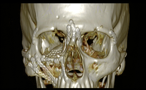
The method is explained clinically and technically in a stepwise manner using the case of a 39-year-old male patient who was involved in a car accident, resulting in a Le Fort III fracture in combination with a severely comminuted orbito-zygomatic fracture on the right side and a non-comminuted and slightly displaced orbito-zygomatic fracture on the left side diagnosed by the initial CT scan performed in the emergency room on the day of the accident ().
Figure 1. Pre-operative 3D CT scan showing a right Le Fort III fracture in combination with a severely comminuted orbito-zygomatic fracture and a left non-comminuted and slightly displaced orbito-zygomatic fracture.
The complete intra-operative procedure was performed according to the following protocol:
1. Surgical repair of the non-comminuted left side
The operation was performed under general anesthesia. Upon admission, the patient was placed on parenteral antibiotics (either amoxicillin 1 g TID or amoxicillin and clavulonic acid 1.2 g TID i.v.), which were maintained for 3 days post-operatively.
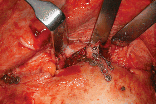
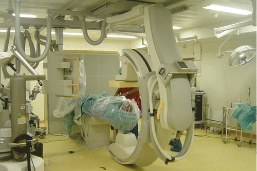
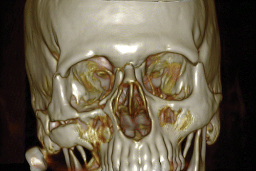
The fractures were exposed by a coronal approach, a gingivobuccal approach, and a combined trans-conjunctival-trans-caruncular approach with lateral canthotomy on the right side. First, per-operative maxillo-mandibular fixation to restore good occlusion was performed using metal arch bars (Dautrey type) applied to the teeth of the maxilla and mandible. Next, the orbito-zygomatic complex on the less-displaced left side was reduced, achieving satisfactory alignment at the left zygomatico-frontal, zygomatico-sphenoid and zygomatico-maxillary sutures, as well as at the inferior orbital rim. The zygomatico-frontal suture was fixed with a titanium plate and monocortical screws (Matrix Midface, Synthes, Oberdorf, Switzerland). Both naso-maxillary medial buttresses were then reduced and fixed to the frontal bar by means of three titanium plates (). At this stage, five 4-mm screws (Matrix Midface, Synthes) were applied to the skull to facilitate further patient registration. The patient was then covered with sterile plastic sheets to protect the operating field for the CBCT scan ().
2. Intra-operative mobile C-arm CBCT scan with flat-panel detector
Imaging was performed with a Philips Allura Xper FD20 (Philips Healthcare, Best, The Netherlands) using a low-dose XperCT protocol. The system was equipped with the MRC-GS X-ray tube (120 kV, 260 mAS, and pulse-width 5 ms). Three hundred and ten sequential planar projection images were acquired through 240° (rotation time: 10 sec; rotation speed: 24 degrees/sec). A flat-panel detector (matrix size: 30 × 40 cm; pixel pitch: 154 µm; resolution: 2360 × 1920 pixels; dynamic range: 14-bit) was integrated into the system. This detector is composed of the following layers: (1) a scintillator detection layer of cesium iodide (CsI) that converts the X-ray photons into luminous photons; (2) a TFT (Thin-Film Transistor) photodiode array of amorphous silicon (a-Si) that transforms luminous photons into an electric signal; and (3) a glass substrate that corrects temporal artifacts. The images were transferred first to the FD 20 Allura workstation in DICOM format and then to the 3D Xtra-Vision workstation. Here, the 3D volumetric reconstruction of images was performed by back-projection into a V3D format. The spatial resolution of the reconstructed volume images was 256 × 256 × 256 voxels. (Procedure duration: 2 minutes.)
3. “Mirroring” computational planning
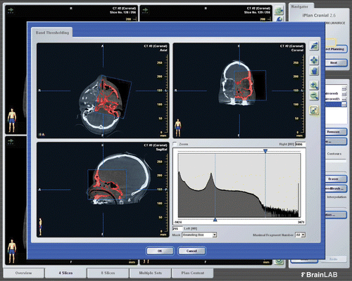
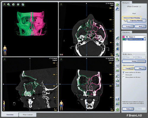
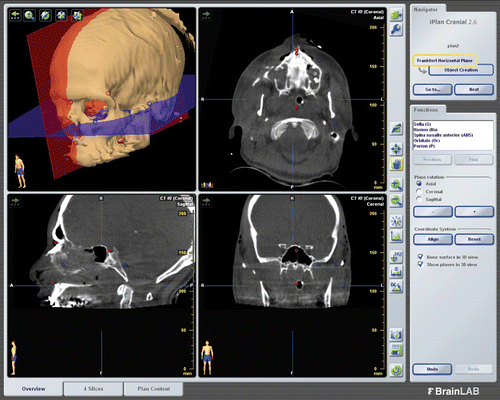
Scanned DICOM images were imported to the BrainLAB format using the iPlan®Cranial Version 2.6 software platform (BrainLAB AG, Feldkirchen, Germany). Five anatomical landmarks (the nasion, sella, porion, orbitale and spina nasalis anterior) were then determined to define the horizontal Frankfort and mid-sagittal planes to re-align the patient data symmetrically (). A semi-automatic segmentation of the volumetric region of interest was performed on axial, coronal and sagittal reconstruction images windowed into bone-specific Hounsfield units using a specific cursor, thereby acquiring a 3D template of the freshly repaired left orbito-zygomatic fracture (). The newly generated template was mirrored and superimposed on the right fractured side in two and three dimensions in the original CT scans, resulting in an ideal and symmetrical positioning of the bones (). The mirrored images were then manually adjusted to fit as precisely as possible to the fixed anatomical landmarks, such as the pterygoid plates and the petrous apex of the temporal bone. The new data sets of the treatment plan were loaded and exported to the VectorVision Cranial 7.8 navigation software platform (BrainLAB AG) for intra-operative imaging. (Procedure duration: 15 minutes.)
Figure 4. Intra-operative planning. Determination of five anatomical landmarks (the nasion, sella, porion, orbitale and spina nasalis anterior) to define the horizontal Frankfort (blue) and mid-sagittal (red) planes in order to re-align the patient data symmetrically.
4. Navigation setting
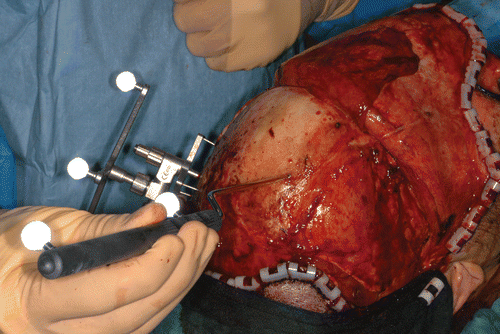
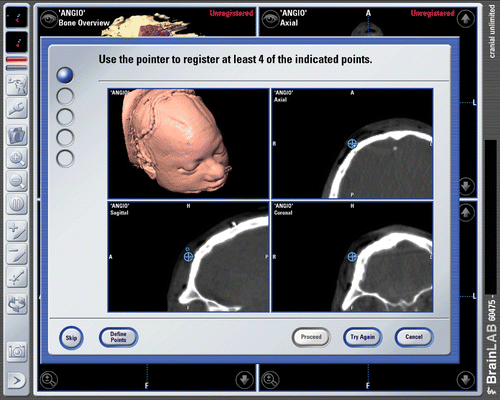
A reference star array with three passive disposable reflective marker spheres was directly fixed with a 1.5-mm screw to the patient's parietal skull to provide references for navigation. Patient registration was then performed by indicating the five screw-head markers to the navigation system with a blunt-tip pointer with two reflective marker spheres ( and ). (Procedure duration: 5 minutes.) Once the patient registration, as well as its accuracy, had been verified, the operation was continued.
5. Surgical repair of the comminuted right side
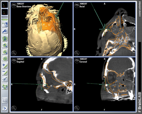
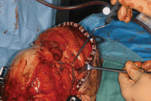
The displaced bones were mobilized and reduced into the desired position by using a T-shaped 2.7-mm tap placed transcutaneously on the tip of the malar eminence in the right orbito-zygomatic complex fracture. The 3D positioning and matching between the planned and actual position of the reduced bone were verified by means of a blunt-tipped pointer ( and ). The fractures were then fixed, in accordance with the planned position, using titanium plates and a monocortical screw system. A 3D preformed MatrixORBITAL mesh (Synthes) was selected according to the size of the defect as previously measured on the pre-operative CT-scan, and used to reconstruct the left orbital medial wall and floor.
6. Postsurgical CBCT scan and fusion with intra-operative planning images
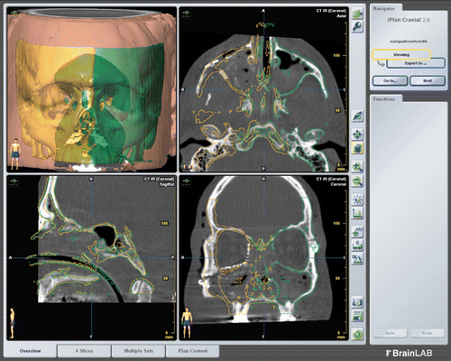
Before definitive closure of the incision, the patient was again covered with sterile plastic sheets and an intra-operative CBCT scan was performed. The actual CBCT images were superimposed on the pre-operative planning images for comparison and to confirm ideal placement of the bone as previously planned ( and ). (Procedure duration: 2 minutes.)
Figure 11. Superimposition of the pre-operative planning images (yellow) on the immediate intra-operative CT-scan images (white), showing the ideal placement of the orbito-zygomatic complex and the ideal reconstruction of the orbital floor and medial wall by using a 3D preformed mesh as previously planned.
7. Surgical closure
The periorbita was sutured to the periosteum over the inferior orbital rim using uninterrupted 5–0 Vicryl sutures. The inferior conjunctiva was closed with a running 6–0 Maxon suture, and the intraoral incision with a running 4–0 Vicryl suture. The coronal incision was closed in two layers; the galea with uninterrupted 2–0 Vicryl and the scalp with staples.
Discussion
The ultimate goal in the management of midfacial fractures is the restoration of pre-traumatic function and aesthetics Citation[14–17]. The achievement of these two outcomes is often challenging, especially when using conventional surgical techniques without the aid of new computational and imaging technologies. Flattening of the malar eminence due to medial rotation of the zygomatic body, increased facial width due to a lateral rotation of the zygomatic arch, and enophthalmos, often resulting in a handicapping diplopia due to increased orbital volume secondary to an insufficient reduction of the lateral wall and telecanthus, represent the most classical sequelae to inadequate treatment of such fractures Citation[14–17]. An accurate primary restoration is thus of paramount importance, if not mandatory, given the poorer outcome often associated with secondary reconstruction of midfacial post-traumatic deformities.
As previously discussed, CAS has improved current surgical practices and patient outcomes in the treatment and prevention of such deformities Citation[1–13]. The advantages and disadvantages of every reported technique implemented in the craniomaxillofacial area are already well documented in the literature and a detailed analysis is beyond the scope of this paper. Our focus is on a particular approach involving the use of “mirroring” assisted planning Citation[4–13]. We recently demonstrated that the application of pre-operative “mirroring” computational planning coupled with a navigation system and an intra-operative mobile C-arm CBCT scan with a flat-panel detector was associated with encouraging results in the treatment of primary and secondary repairs of complex midfacial fractures Citation[13]. The greatest advantage of this approach is that the surgeon can visualize in three dimensions where the fractured bone should be moved to achieve symmetry with respect to the uninjured side. So far, the main disadvantage of this approach has been that, in theory, “mirroring” can only be applied to unilateral cases, given the requirement for a healthy side to serve as a reference in obtaining good facial symmetry. In reality, as reported here, this technique can also be used in particular bilateral cases, provided that (1) one side is not severely or comminutedly fractured and can be first repositioned by a conventional technique under direct visual control, and (2) a CT or CBCT scan is integrated in the operating room and coupled with a navigation system. Thus, the aim is to transform a bilateral fracture into a unilateral fracture by reducing and fixing the less severely fractured side and using this temporary situation as a starting point for proceeding to the classical mirroring planning. The main alteration, as compared to the previously described technique, is that the whole procedure is performed in the operating room, thus eliminating the classical pre-operative step.
The main advantage of this approach is the ability to adapt the surgical strategy à la carte intra-operatively by integrating three CAS technologies which allow for (1) accurate, predictable and precise 3D bone repositioning according to the computational simulation, even in bilateral fractures; and (2) immediate and rapid evaluation of the adequacy of the bone repositioning by superimposition of the actual images on the pre-operative computational templates for comparison. This avoids the need for further surgical revisions, which entail additional costs and potentially increase medical and surgical morbidity.
Other strengths of this approach are that the patient-specific intra-operative “mirroring” planning may be rapidly developed (in approximately 15 minutes) and that only very basic computer knowledge is needed to achieve efficiency and independence with the software. However, clear drawbacks are (1) the high costs of the radiological, mirroring and navigation hardware and software; (2) the need for experienced radiological and operating-room staff to enable good results; and (3) the use of operating-room time, albeit limited, for the entire planning procedure. Furthermore, sufficient mirroring experience with unilateral primary and secondary cases is recommended before applying the described technique. To the best of our knowledge, Pohlenz et al. Citation[18] are the only group to have reported on the clinical use of an intraoperative CBCT scan with an integrated flat-panel detector for the evaluation of the surgical treatment of orbito-zygomatic fractures. In contrast to our protocol, they managed the fractures using conventional techniques without employing either computational pre-operative planning or an intra-operative surgical system.
Concerning the management of midfacial bilateral fractures, Schramm et al. recently described a new technical approach for pure bilateral orbital floor fractures Citation[19]. They first carried out the usual pre-operative planning by correctly mirroring the non-fractured orbital frame. A computational template was then generated with several bony gaps within the orbital floor, which were bridged by importing sub-volumes of standard reference CT datasets into the template. These sub-volumes were manually oriented until the best possible surgical template was achieved. The obvious advantage of this technique is that the planning is carried out pre-operatively without time pressure. In terms of complexity, however, we believe that our modus operandi is simpler because it is a straightforward variation on the usual mirroring planning applied in craniomaxillofacial surgery.
Despite the short follow-up period (9 months), we consider that intra-operative imaging and mirroring planning combined with navigational guidance in the presented patient was successful, with excellent cosmetic and psychological results. Therefore, this treatment appears to be a promising alternative to conventional techniques for the reconstruction of bilateral midfacial fractures and the re-establishment of facial symmetry.
Declaration of interest: The authors report no declarations of interest.
References
- DiGioia AM, 3rd, Jaramaz B, Colgan BD. Computer assisted orthopaedic surgery. Image guided and robotic assistive technologies. Clin Orthop Relat Res 1998; (354): 8–16
- Simon DA, Lavallée S. Medical imaging and registration in computer assisted surgery. Clin Orthop Relat Res 1998; (354): 17–27
- Taylor RH, Lavallée S, Burdea GC, Mösges R. Computer-integrated surgery. Technology and clinical applications. Clin Orthop Relat Res 1998; (354): 5–7
- Gellrich NC, Schramm A, Hammer B, Rojas S, Cufi D, Lagreze W, Schmelzeisen R. Computer-assisted secondary reconstruction of unilateral posttraumatic orbital deformity. Plast Reconstr Surg 2002; 110(6)1417–1429
- Watzinger F, Wanschitz F, Wagner A, Enislidis G, Millesi W, Baumann A, Ewers R. Computer-aided navigation in secondary reconstruction of post-traumatic deformities of the zygoma. J Craniomaxillofac Surg 1997; 25(4)198–202
- Stanley RB, Jr. Use of intraoperative computed tomography during repair of orbitozygomatic fractures. Arch Facial Plast Surg 1999; 1(1)19–24
- Klug C, Schicho K, Ploder O, Yerit K, Watzinger F, Ewers R, Baumann A, Wagner A. Point-to-point computer-assisted navigation for precise transfer of planned zygoma osteotomies from the stereolithographic model into reality. J Oral Maxillofac Surg 2006; 64(3)550–559
- Westendorff C, Gulicher D, Dammann F, Reinert S, Hoffmann J. Computer-assisted surgical treatment of orbitozygomatic fractures. J Craniofac Surg 2006; 17(5)837–842
- Fuller SC, Strong EB. Computer applications in facial plastic and reconstructive surgery. Curr Opin Otolaryngol Head Neck Surg 2007; 15(4)233–237
- Pham AM, Rafii AA, Metzger MC, Jamali A, Strong EB. Computer modeling and intraoperative navigation in maxillofacial surgery. Otolaryngol Head Neck Surg 2007; 137(4)624–631
- Xia JJ, Gateno J, Teichgraeber JF. A new paradigm for complex midface reconstruction: A reversed approach. J Oral Maxillofac Surg 2009; 67(3)693–703
- Bell RB, Markiewicz MR. Computer-assisted planning, stereolithographic modeling, and intraoperative navigation for complex orbital reconstruction: A descriptive study in a preliminary cohort. J Oral Maxillofac Surg 2009; 67(12)2559–2570
- Scolozzi P, Terzic A, “Mirroring” computational planning, navigation guidance system and intra-operative mobile C-arm cone-beam CT with flat-panel detector: A new rationale in primary and secondary treatment of midfacial fractures? J Oral Maxillofac Surg (In press)
- Ellis E, 3rd, el-Attar A, Moos KF. An analysis of 2,067 cases of zygomatico-orbital fracture. J Oral Maxillofac Surg 1985; 43(6)417–428
- Gruss JS, Van Wyck L, Phillips JH, Antonyshyn O. The importance of the zygomatic arch in complex midfacial fracture repair and correction of posttraumatic orbitozygomatic deformities. Plast Reconstr Surg 1990; 85(6)878–890
- Gruss JS. Complex craniomaxillofacial trauma: Evolving concepts in management. A trauma unit's experience – 1989 Fraser B. Gurd lecture. J Trauma 1990; 30(4)377–383
- Markowitz BL, Manson PN. Zygomatic complex fractures. Manual of Internal Fixation in the Cranio-Facial Skeleton, J Prein. Springer-Verlag, Berlin 1998; 133–138
- Pohlenz P, Blake F, Blessmann M, Smeets R, Habermann C, Begemann P, Schmelzle R, Heiland M. Intraoperative cone-beam computed tomography in oral and maxillofacial surgery using a C-arm prototype: First clinical experiences after treatment of zygomaticomaxillary complex fractures. J Oral Maxillofac Surg 2009; 67(3)515–521
- Schramm A, Suarez-Cunqueiro MM, Rucker M, Kokemueller H, Bormann KH, Metzger MC, Gellrich NC. Computer-assisted therapy in orbital and mid-facial reconstructions. Int J Med Robot 2009; 5(2)111–124
