
Abstract
Computer models capable of predicting elbow flexion and extension range of motion (ROM) limits would be useful for assisting surgeons in improving the outcomes of surgical treatment of patients with elbow contractures. A simple and robust computer-based model was developed that predicts elbow joint ROM using bone geometries calculated from computed tomography image data. The model assumes a hinge-like flexion-extension axis, and that elbow passive ROM limits can be based on terminal bony impingement. The model was validated against experimental results with a cadaveric specimen, and was able to predict the flexion and extension limits of the intact joint to 0° and 3°, respectively. The model was also able to predict the flexion and extension limits to 1° and 2°, respectively, when simulated osteophytes were inserted into the joint. Future studies based on this approach will be used for the prediction of elbow flexion-extension ROM in patients with primary osteoarthritis to help identify motion-limiting hypertrophic osteophytes, and will eventually permit real-time computer-assisted navigated excisions.
Introduction
In primary elbow osteoarthritis, terminal range of motion (ROM) is limited by bone-on-bone impingement due to hypertrophic osteophytes [Citation1, Citation2]. Open or arthroscopic surgical debridement is commonly performed to remove osteophytes that are impeding motion and causing pain [Citation3–6].
Computed tomography (CT) imaging is commonly used clinically by surgeons for static assessment of possible locations of bone impingement. Dynamic assessment of impingement with computer models, derived from CT data, which can simulate the ROM of healthy and arthritic elbows would be useful surgical planning tools. Such models would allow pre-operative assessment of which osteophytes actually limit ROM, and the anticipated increase in ROM if those osteophytes were to be resected. Such pre-operative planning would allow for more efficient and possibly less invasive surgical treatment, and may lead to the development of newer navigation-assisted debridement techniques [Citation7]. Sophisticated models for the prediction of elbow joint kinematics have been reported previously in the literature [Citation8–16]. Some models are limited to hinge-like movement [Citation8–11, Citation13, Citation15], while others allow full three-dimensional (3D) kinematics as a function of subject-specific contact geometry and soft tissue constraint [Citation14, Citation16]. None of these models, however, have been directly evaluated through comparison with companion experimental results.
The purpose of this study was to evaluate a computer modeling technique for predicting passive elbow flexion-extension ROM based on impingement of bony geometry, derived from CT images. The accuracy of the technique was assessed through direct comparison of computer-simulated and experimental results for a single elbow specimen with and without simulated impinging hypertrophic osteophytes.
Methods
Specimen preparation
One fresh-frozen human left arm (from a male subject, aged 75 years) amputated at the mid-humeral shaft was used for all experiments and computer simulations. CT images of the arm were obtained using a GE Discovery CT750 HD scanner (GE Healthcare, Pewaukee, WI) at 120 kV and 200 mA. The resulting voxel dimensions were 0.625 × 0.391 × 0.391 mm, with the longest voxel dimension being aligned with the long axis of the humerus and forearm. The specimen had no CT or visual evidence of elbow arthritis or prior surgery. The radius and ulna were pinned together with the forearm positioned in neutral rotation, thereby allowing the forearm to be considered a single rigid body for all subsequent experiments and simulations.
Apparatus
The proximal end of the humerus was potted in a plastic cylinder using Denstone dental cement (Heraeus Kulzer, South Bend, IN), and the cylinder was rigidly clamped to an elbow testing apparatus (). Pneumatic actuators applied tensile forces to cables sutured to the biceps, brachialis, and triceps muscles of the specimen, routed through pulleys to follow physiological lines of action.
Figure 1. The specimen mounted on an elbow testing apparatus in the horizontal position. Threaded pins were used to lock the forearm in neutral rotation. Markers for the Optotrak Certus® motion tracking system were affixed to the humerus clamp and the ulna.
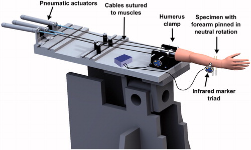
Infrared marker triads were affixed to the ulna bone and humerus clamp, and were tracked using an Optotrak Certus® optical motion-capture system (Northern Digital Inc., Waterloo, Ontario). Anatomical features, including the trochlea and capitellum of the humerus, and the greater sigmoid notch of the ulna, were traced using an optically tracked stylus tool, which recorded the position of the stylus tip with respect to the corresponding bone (humerus or ulna). Elbow flexion was defined as rotation of the forearm about an anatomic flexion-extension (FE) axis defined by a line connecting the center of a sphere fitted to the capitellum trace and a circle fitted to the trochlea trace [Citation17, Citation18], with full extension defined as 0° of flexion. The location of the center of a circle fitted to the greater sigmoid notch trace (GSN) was also calculated.
Range of motion measurement
The passive flexion range of motion of the specimen was measured under three different conditions:
(a) Intact: The skin, muscles, and capsuloligamentous structures were left intact.
(b) Capsulectomy: The skin, muscle body, and capsule were removed in order to eliminate soft tissue impingement.
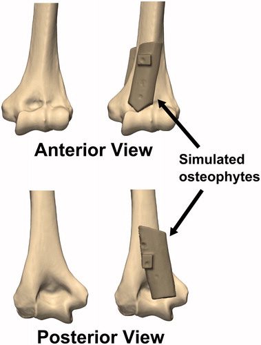
(c) Osteophyte: Rectangular cortical bone blocks measuring approximately 20 mm × 60 mm × 5 mm were harvested from the humeral shaft of another cadaveric specimen. An orthopaedic oscillating saw was used to shape the bone blocks into simulated anterior and posterior osteophytes, which were then affixed to the anterior and posterior surfaces of the distal humerus using imaging-compatible nylon nuts and bolts, such that the olecranon and coronoid fossae were partially obstructed ().
Figure 2. Simulated osteophytes made from harvested cortical bone were affixed to the anterior and posterior surface of the distal humerus. The simulated osteophytes were positioned such that they would partially obstruct the coronoid and olecranon fossae and impinge with the coronoid and olecranon tips during flexion and extension motions, respectively.
The arm was oriented in a horizontal configuration (). To stabilize the elbow joint, muscle tensions were applied by the simulator at ratios designed to balance the flexion and extension moments across the joint (biceps = 20 N; brachialis = 20 N; triceps = 40 N) [Citation19]. These loads are smaller than the physiological loads required to move the joints [Citation20], but were chosen to prevent potential pull-out failure of the suture attachments. The elbow joint was taken manually through passive flexion and extension motions by one of the investigators (M.N.) at a rate of approximately 60°/s. The investigator removed his hand from the arm when the end point of motion was achieved, such that only gravity loads were acting on the forearm when the motion limits were recorded. The distance from the GSN to the FE axis was also collected throughout all flexion and extension motions. This distance was used as a metric for measuring ulnohumeral joint distraction or subluxation, which could occur as the result of reduced soft tissue constraint after capsule removal.
Each motion was repeated 5 times, and the averages and standard deviations of the maximum flexion and extension values across the 5 trials with the specimen in the intact, capsulectomy, and osteophyte conditions were calculated. In the capsulectomy and osteophyte conditions, non-physiologic subluxation could occur. An alternative criterion was established in order to delineate physiologic ROM before subluxation occurs from pathologic ROM beyond the physiologic range which results from joint subluxation. At any angle, if the GSN to FE axis distance suddenly deviated from the corresponding GSN to FE distances measured during the intact trials, the joint was assumed to be undergoing non-physiological subluxation, with the physiologic ROM limit having been reached: further flexion or extension was considered pathologic.
Following the ROM measurements, the arm was disarticulated and denuded of all soft tissues. Spherical 20-mm nylon fiducial markers were attached to the humerus and ulna, and their locations relative to the corresponding trackers attached to the bones were recorded using an optically tracked stylus. CT images of the denuded bones with simulated osteophytes were obtained using the same scanner and scanning protocol as above.
Simulation model development
Three-dimensional (3D) models of the intact and osteophyte elbow joints were created from the pre- and post-experiment CT scans, respectively. Bony geometry was extracted using threshold segmentation at +226 HU, wrapped, and smoothed using Mimics software (Materialise, Leuven, Belgium). The models were then exported as triangulated stereolithography (STL) files. The intact bone geometries were registered to the osteophyte bone geometries using an iterative closest point (ICP) algorithm. The fiducial markers were also segmented from the post-experiment CT images, and their positions were calculated using a sphere fit.
With the fiducial locations known in the CT and laboratory data, all of the bone models (intact and osteophyte) could be transformed to their experimentally measured positions. The bones of the computer model were reassembled to match the bone positions at approximately 45° of flexion during the experiment. These models were imported into the SolidWorks computer aided design (CAD) software package (Dassault Systèmes SolidWorks Corp., Waltham, MA) using the ScanTo3D module, which automatically converts triangulated surfaces into CAD solid bodies.
Computer ROM prediction
Elbow flexion and extension motions were simulated for the intact and osteophyte bone geometries using a SolidWorks Motion Study computational model. A hinge-like cylindrical FE axis was assumed, using the same anatomical FE axis as described above. The joint permitted FE rotation as well as medial-lateral translation. A flexion moment of ±3 Nm (where positive = flexion) was applied to the forearm about the FE axis defined on the humerus, which resulted in elbow flexion or extension motions from the initial 45° alignment. This applied moment was analogous to the moment caused by gravity acting on the forearm at the flexion or extension limits during the experiments, calculated from the measured dead-weight of the forearm at the wrist. The software was able to detect contact between bones at the extremes of motion, and impingement restricted any further motion, at which point the ROM was recorded. Motions were calculated using the default Gear stiff (GSTIFF) integrator [Citation21], and contact was modeled using an impact (penalty regularization) method with high contact stiffness (1E9 N/mm). The flexion moment was decreased and increased by an order of magnitude (to 0.3 Nm and 30 Nm, respectively) for the intact model to determine if the ROM results were sensitive to the applied moment.
Results
During the 5 flexion and extension motions with the intact joint, the average (±1 standard deviation) range of motion before bony impingement occurred was 0 ± 1° in extension and 158 ± 1° in flexion. Deviation of the GSN from the FE axis was typically less than 2 mm (), indicating that the joint maintained congruency throughout the arc of motion.
Figure 3. Deviation of the center of a circle fitted to the greater sigmoid notch of the ulna (GSN) from the flexion-extension (FE) axis defined by the center of a circle fitted to the trochlea and a sphere fitted to the capitellum of the distal humerus. Larger deviations indicate that the ulnohumeral joint is undergoing non-physiologic subluxation. Shaded regions indicate the mean ±1 standard deviation of the corresponding data gathered during all trials.
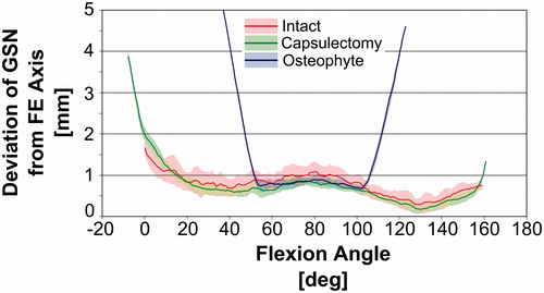
After the capsulectomy, the average range of motion before bony impingement was −8 ± 1° in extension and 160 ± 1° in flexion. Based on visual inspection of the data presented in , the deviation of the GSN from the FE axis followed a pattern similar to that for the intact joint throughout most of the flexion-extension ROM. The deviation increased sharply near 0° during extension and 159° during flexion, indicating non-physiological subluxation and that the physiologic ROM had been met.
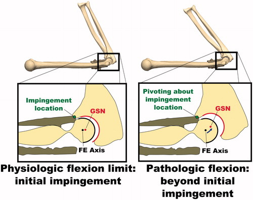
After implanting the simulated osteophytes, the average range of motion before bony impingement was 38 ± 1° in extension and 119 ± 2° in flexion. Again, the deviation of the GSN from the FE axis followed a pattern similar to that for the intact joint for a portion of the flexion-extension ROM; however, the deviation increased sharply at approximately 54° during extension and 102° during flexion, indicating non-physiological subluxation and that the physiologic ROM had been met. Non-physiologic subluxation was confirmed visually by reconstructing the bone positions at the physiologic and pathologic full flexion angles during the osteophyte experiments ().
Figure 4. Illustration of non-physiologic subluxation of the ulnohumeral joint during flexion motions with simulated osteophytes attached. The deviation of the GSN from the FE axis is small at initial impingement when the physiologic flexion limit is met, but increases as the flexion angle is increased further. While this pathologic flexion motion occurs, the joint is hinging about the impingement point on the osteophyte, rather than the FE axis.
The flexion and extension ROM limits for the intact and osteophyte geometries were also calculated using the computational model (0°–161° and 53°–104°, respectively). Using a 10× lower (0.3 Nm) or 10× higher (30 Nm) flexion moment caused the simulation-predicted flexion-extension arc of the intact model to decrease by 0.4° (−0.2%) or increase by 0.3° (0.2%), respectively. Visual inspection of the simulation results confirmed that bone to bone impingement of the coronoid process against the coronoid fossa had occurred at full flexion, while impingement of the olecranon against the olecranon fossa occurred at full extension ().
Figure 5. Examination of the simulation-predicted impingement locations. Flexion was limited by impingement of the coronoid process in the coronoid fossa. Extension was limited by impingement of the olecranon in the olecranon fossa.

summarizes the experimentally measured ROM limits for the intact, capsulectomy, and osteophyte conditions, as well as the computer-predicted ROM limits. When pathologic subluxation is used as a criterion for establishing the maximum flexion or extension range of motion, agreement between the experiment and simulation improves.
Table I. Elbow range of motion measured during experiments and simulated by the computer model. Experiment ROM represents the average ROM at bony impingement measured across 5 flexion and extension trials. The physiologic ROM was based on the ROM before non-physiological joint subluxation occurred, determined through visual inspection of .
Discussion
The simulation-predicted extension and flexion limits for the intact joint were close to the mean experimentally measured limits (differences of 0° and 3°, respectively). These differences are likely not clinically significant, as Armstrong et al. [Citation22] found that average differences in intra-observer measurements of elbow flexion and extension angles using a manual goniometer by trained observers ranged between 2.4° and 4.9°, while inter-observer differences were even higher. The simulation-predicted osteophyte model ROM envelope was smaller than the absolute ROM measured during the experiment (51° versus 81°). This was because non-physiologic hinging of the joint occurred as the native ulna contacted the simulated osteophyte. This joint hinging was confirmed with the optical tracking data. However, when non-physiologic subluxation was used as a metric to identify joint ROM limits, the experimentally measured ROM envelope was in close agreement with the simulation ROM prediction (respectively 54° versus 53° for extension, and 102° versus 104° for flexion).
The experimentally measured ROM results before and after the capsulectomy offer justification for adopting the subluxation-based ROM limit criteria. The capsulectomy caused an increase in the ROM envelope; however, this increase in ROM was accompanied by large deviations of the GSN from the FE axis (subluxation). The approximate angles at which the subluxation began to occur were very close to the extension and flexion ROM limits of the intact joint (within 1°). The capsulectomy was performed during the experiment, but the capsule would normally be intact and would resist subluxation of joints presenting with hypertrophic osteophytes. Based on this, we can assume that the subluxation-based ROM limits are likely closer to the ROM limits of a joint when the capsuloligamentous structures are left intact, and that the absolute extension and flexion limits measured during our experiment were artificially exaggerated by removal of these structures.
During the simulations, the applied flexion moment was ±3 Nm in order to agree with the gravity-only loading at the flexion and extension limits during the experiment. The predicted ROM limits were not sensitive to this value, with the overall flexion arc changing by only 0.4° or less after order-of-magnitude changes in the applied moment. This suggests that our choice of simulated loading was justified.
The computer model assumed that forearm motion was solely due to rotation about a cylindrical flexion axis passing through the center of the trochlea and capitellum of the humerus. The results suggest that assuming a hinge-like motion was valid for the flexion-extension motions considered in this study, assuming that the capsuloligamentous structures remain intact. Most previous computer models of the elbow have neglected to consider subject-specific bony geometry, and are thus incapable of predicting bony impingements. More recently, sophisticated elbow models [Citation14, Citation16] have featured subject-specific bony geometry, but have also included simulated soft tissues to provide constraint. The geometry and mechanical properties of these soft tissues cannot be obtained from CT imaging. In comparison to such models, our model is much easier to create, more robust, and computationally efficient; however, it is unable to simulate the effects of soft-tissue resection or repair.
Clinically, ROM may be limited by contracture of the joint capsule, collateral ligaments and muscles, weakness, or pain, as well as by impingement of the bones or osteophytes. The presented model is only capable of measuring ROM limits due to bony impingement. However, this modeling technique could form the basis of a pre-operative planning technique where osteophyte removal is simulated and resulting increases in joint ROM are predicted. Such a tool would enable surgeons to focus surgery on only those osteophytes which are actually limiting joint ROM, resulting in a more efficient and potentially less invasive procedure. This technique could also be employed for navigation-assisted debridement such as the technique employed by Ikeda et al. [Citation7].
The experimental results support the validity of the computer model; however, only one non-pathological specimen was employed and simulated osteophytes were manufactured. Future work will compare computer-predicted and clinically measured ROM limits of healthy and pathological joints.
In summary, a simple and robust computer-based method for predicting elbow flexion and extension ROM limits with and without hypertrophic osteophytes was developed and validated against experimental results with a cadaveric specimen. Future studies based on this approach will be used for the prediction of elbow flexion-extension ROM in patients with hypertrophic osteophytes and to develop 3D osteophyte maps [Citation23], which should eventually permit real-time computer-assisted navigated excision.
Declaration of interest
Dr. Willing was supported in part by the Joint Motion Program – A CIHR Training Program in Musculoskeletal Health Research and Leadership.
References
- Gramstad GD, Galatz LM. 2006. Management of elbow osteoarthritis. J Bone Joint Surg Am 88:421–30
- Soojian MG, Kwon YW. 2007. Elbow arthritis. Bull NYU Hosp Jt Dis 65:61–71
- Oka Y, Ohta K, Saitoh I. 1998. Debridement arthroplasty for osteoarthritis of the elbow. Clin Orthop Relat Res 351:127–34
- Antuna SA, Morrey BF, Adams RA, O’Driscoll SW. 2002. Ulnohumeral arthroplasty for primary degenerative arthritis of the elbow: long-term outcome and complications. J Bone Joint Surg Am 84:2168–73
- Wada T, Isogai S, Ishii S, Yamashita T. 2004. Debridement arthroplasty for primary osteoarthritis of the elbow. J Bone Joint Surg Am 86:233–41
- Adams JE, Wolff LH 3rd, Merten SM, Steinmann SP. 2008. Osteoarthritis of the elbow: results of arthroscopic osteophyte resection and capsulectomy. J Shoulder Elbow Surg 17:126–31
- Ikeda M, Kobayashi Y, Saito I, et al. 2012. Navigation-assisted debridement arthroplasty for osteoarthritis of the elbow: A preliminary report. Shoulder & Elbow 4:72–6
- Raikova R. 1992. A general approach for modelling and mathematical investigation of the human upper limb. J Biomech 25:857–67
- Gonzalez RV, Hutchins EL, Barr RE, Abraham LD. 1996. Development and evaluation of a musculoskeletal model of the elbow joint complex. J Biomech Eng 118:32–40
- Lemay MA, Crago PE. 1996. A dynamic model for simulating movements of the elbow, forearm, and wrist. J Biomech 29:1319–30
- Garner BA, Pandy MG. 2001. Musculoskeletal model of the upper limb based on the visible human male dataset. Comput Methods Biomech Biomed Engin 4:93–126
- Triolo RJ, Werner KN, Kirsch RF. 2001. Modeling the postural disturbances caused by upper extremity movements. IEEE Trans Neural Syst Rehabil Eng 9:137–44
- Holzbaur KR, Murray WM, Delp SL. 2005. A model of the upper extremity for simulating musculoskeletal surgery and analyzing neuromuscular control. Ann Biomed Eng 33:829–40
- Fisk JP, Wayne JS. 2009. Development and validation of a computational musculoskeletal model of the elbow and forearm. Ann Biomed Eng 37:803–12
- King MA, Glynn JA, Mitchell SR. 2011. Subject-specific computer simulation model for determining elbow loading in one-handed tennis backhand groundstrokes. Sports Biomech 10:391–406
- Spratley EM, Wayne JS. 2011. Computational model of the human elbow and forearm: application to complex varus instability. Ann Biomed Eng 39:1084–91
- Morrey BF, Chao EY. 1976. Passive motion of the elbow joint. J Bone Joint Surg Am 58:501–8
- Ericson A, Arndt A, Stark A, et al. 2003. Variation in the position and orientation of the elbow flexion axis. J Bone Joint Surg Br 85:538–44
- Morrey BF, Tanaka S, An KN. 1991. Valgus stability of the elbow. A definition of primary and secondary constraints. Clin Orthop Relat Res 265:187–95
- An KN, Hui FC, Morrey BF, Linscheid RL, Chao EY. 1981. Muscles across the elbow joint: a biomechanical analysis. J Biomech 14:659–69
- Gear CW. 1971. The automatic integration of ordinary differential equations. Commun ACM 14:176–9
- Armstrong AD, MacDermid JC, Chinchalkar S, et al. 1998. Reliability of range-of-motion measurement in the elbow and forearm. J Shoulder Elbow Surg 7:573–80
- Nishiwaki M, Willing R, Johnson JA, et al. 2013. Identifying the location and volume of bony impingement in elbow osteoarthritis by 3-dimensional computational modeling. J Hand Surg Am 38:1370–6