
Abstract
Objective: In total hip arthroplasty, it is important to assess postoperative implant orientation. The computed tomography-based (CT-based) three-dimensional (3D) templating method using 3D preoperative planning software is generally recommended. In this method, postoperative implant orientation within a bony coordinate system can be measured by overlaying a 3D computerized model of the implant on a real postoperative CT image of the implant. The bony coordinate system consists of several reference points (RPs) marked on a CT image of the bone surface. Therefore, preoperative and postoperative coordinate systems do not always match. We investigated how the difference between coordinate systems constructed from RPs chosen by manual methods (M1 and M2) and those constructed by the computer matching method influences the results of measurement validation.
Methods: In M1, postoperative RPs were chosen without a specific tool in a single planning module. In M2, postoperative RPs were chosen with as little deviation as possible from preoperative RPs, verifying preoperative RPs on another monitor.
Results: M1 and M2 produced mean errors in acetabular cup inclination of 0.7° ± 0.5° and 0.5° ± 0.3°, respectively, and mean errors in cup anteversion of 1.3° ± 1.2° and 0.5° ± 0.4°, respectively, which were statistically significant differences. M1 and M2 produced mean errors in femoral stem anteversion of 2.4° ± 2.0° and 2.7° ± 2.1°, respectively, not a significant difference, but these errors were larger than errors in cup orientation.
Discussion: We recommend referring to preoperative RPs when choosing postoperative RPs. Surgeons must be aware that for evaluation of postoperative stem anteversion, manual methods may produce considerable error.
Introduction
In total hip arthroplasty (THA), implant malposition is known to lead serious complications such as dislocation, mechanical loosening, wear or breakage of the polyethylene liner, metallosis or metal ion release from metal-on-metal bearings, and squeaking or breakage of ceramic-on-ceramic bearings.[Citation1–6] Therefore, it is recommended that in modern THA with a conventional femoral head size,[Citation7] surgeons use an inclination of 40–45° and anteversion based on combined anteversion theory for acetabular cup orientation, and indeed it has recently been reported that precise implantation prevents such complications.[Citation8,Citation9] Although many helpful techniques have been developed to achieve accurate implantation,[Citation8–14] such as computed tomography-based (CT-based) navigation, imageless navigation, and patient-specific surgical guides, it is also important to assess postoperative implant orientation and the accuracy of these estimation modalities. The CT-based three-dimensional (3D) templating method using 3D preoperative planning software is generally recommended for evaluation of postoperative implant orientation from the point of view of reproducibility.[Citation15–21] In this method, implant orientation to a bony (pelvic or femoral) coordinate system can be measured by overlaying a 3D computer-aided design (CAD) model of the implant on an image of the real implant on multiplanar reconstruction (MPR) CT images. Implantation accuracy is assessed by comparison of the preoperative planning orientation to the bony coordinate system. At this time, bony coordinate systems commonly consist of some referred points on the surface of the bone on a CT image. Therefore, similarity between bony coordinate systems on preoperative and postoperative CT images is not guaranteed. Thus, we investigated how the difference between coordinate systems influences the results of measurement validation.
Materials and methods
Patients
We studied 20 patients (14 women and 6 men) with a mean age of 60 years (range, 35–81 years) who underwent primary THA using a CT-based navigation system (Stryker Hip Navigation System 1.0; Stryker-Leibinger, Freiburg, Germany) in our hospital between January and May 2012. Of those, 18 patients had osteoarthritis due to dysplasia, 1 had primary osteoarthritis, and 1 had avascular necrosis. Twelve patients underwent surgery on the right side, and 8 patients on the left side.
Preoperative planning
In preparation for surgery, we used the planning module of a navigation system. We obtained CT images from the pelvis to the knee joint at a 3-mm pitch and transferred them into the module. First, we had to choose reference points (RPs) on the surface of 3D models to construct coordinate systems (). For the pelvic system, we chose eight RPs: the left anterior iliac spine (LASI) and right anterior iliac spine (RASI), the left pubic tubercle (LPT) and right pubic tubercle (RPT), the left distal-most point of the ischium (LIS) and the right distal-most point of the ischium (RIS), the midpoint of the pubic symphysis (PUB), and sacral midpoint for the pelvic frame (SACR). For the femoral system, we chose for six RPs: the center of the femoral head (FH), the pyriform fossa (FOS), the posterior-most point of the proximal femur (PF), the medial posterior condyle (MFC) and lateral posterior condyle (LFC), and the knee center for the femoral frame (KC).
Figure 1. RPs and coordinate systems for pelvic and femoral bone. RASI and LASI, right and left anterior iliac spines; RPT and LPT, right and left pubic tubercles; RIS and LIS, right and left distal-most points of the ischium; PUB, midpoint of the pubic symphysis; SACR, sacral midpoint for the pelvic frame; FH, center of the femoral head; FOS, pyriform fossa; PF, posterior-most point of the proximal femur; MFC and LFC, medial and lateral posterior condyles; KC, knee center for the femoral frame.
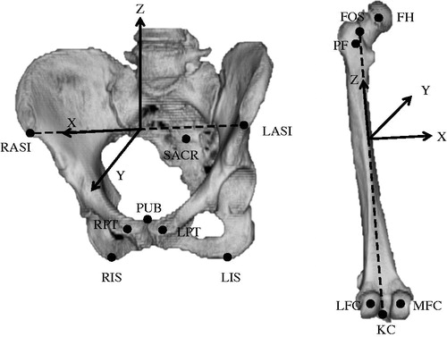
For the pelvic coordinate system, we constructed an anterior pelvic plane (APP) that included the LASI and RASI and the midpoint of the LPT and RPT. The x-axis of the pelvic coordinate system based on the APP was parallel to the line including the LASI and RASI, the y-axis was perpendicular to the APP, and the z-axis was perpendicular to the x- and y-axes. Then, we created the supine functional pelvic plane (FPP) by rotating the APP around the x-axis until the APP was parallel to the CT table in the planning module. We referred to the pelvic coordinate system based on the FPP for cup planning. For the femoral coordinate system, we used the retrocondylar plane, which included three RPs (the PF, the MFC, and the LFC), as a reference plane. After constructing the pelvic and femoral coordinate systems, we tried to fit a 3D template of the implant on the MPR images from preoperative CT images and to determine an optimal type, size, and orientation of implant in relation to the appropriate coordinate system. For preoperative planning, we based the cup target angle on the simplified combined anteversion theory recommended in previous reports.[Citation7,Citation22]
All surgeries were performed via a posterior approach, using the navigation system. For all patients, we used Trident (Stryker, Mahwah, NJ) acetabular cups and Accolade (Stryker) femoral stems. A CT scan was routinely obtained 1 week after surgery in all cases to check for postoperative complications, such as residual leg-length discrepancy, periprosthetic fracture, and hematoma, as well as to confirm implant orientation and position.
Methods for constructing postoperative coordinate systems
Preoperative cup and stem orientations are generally planned on the basis of pelvic and femoral coordinate systems that are constructed with preoperative CT images by 3D planning software. Postoperative cup and stem orientation, however, are measured in relation to the pelvic and femoral coordinate systems newly created from postoperative CT images by the same software. Therefore, it is essential for accuracy to set up preoperative and postoperative bony coordinate systems so that they use a spatial position similar to the corresponding bone model in both preoperative and postoperative CT images. In other words, it is necessary to choose RPs on the postoperative 3D bone model that are in the same positions as corresponding RPs on the preoperative 3D bone model.
We choose two clinical manual methods and one computer matching method as gold standards for selecting RPs on 3D postoperative bone models ( and ). For the first manual method (M1), postoperative RPs were chosen at the prescribed position without a specific tool in one planning module. For the second manual method (M2), postoperative RPs were chosen at a position with as little deviation as possible from preoperative RPs by checking preoperative RPs on another monitor, thus using two planning modules. After surgery, we recorded coordinates for RPs in the postoperative CT coordinate system chosen using M1 and M2 (RPsM1 and RPsM2). Then, the postoperative coordinate systems of the pelvis and femur were constructed using RPsM1 and RPsM2. The affine matrices of the pelvis and femur in the coordinate system of the postoperative CT image created by using RPsM1 and RPsM2 were recorded as Xpm1, Xfm1, Xpm2, and Xfm2 ().
Figure 2. Manual methods for constructing a bony coordinate system on postoperative CT images. These examples are for a pelvic coordinate system. For the first manual method (M1), postoperative RPs, or RPsM1, were chosen at the prescribed position without a specific tool in one planning module. The pelvic coordinate system constructed using RPsM1 was defined by an affine matrix (Xpm1) in the coordinate system of postoperative CT images. For the second manual method (M2), postoperative RPs (RPsM2) were chosen at a position with as little deviation as possible from preoperative RPs by checking preoperative RPs on another monitor. The pelvic coordinate system constructed using RPsM2 was defined by an affine matrix (Xpm2) in the coordinate system of postoperative CT images.
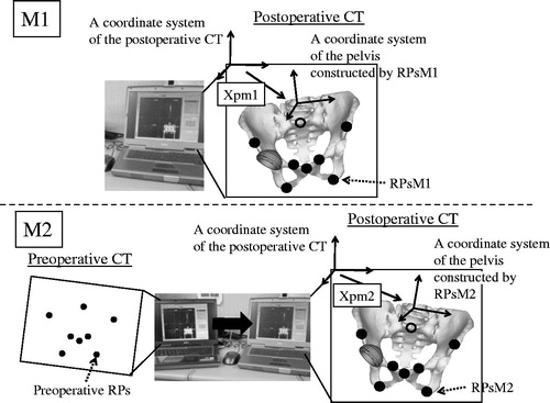
Figure 3. A computer matching method used as a gold standard for constructing a bony coordinate system on postoperative CT images. These examples are for a pelvic coordinate system. The pelvic model on the preoperative CT image was overlaid exactly on the postoperative CT image using the volume registration method. The rotation and translation of the preoperative CT coordinate system during this matching process was recorded as an affine matrix (Tp). The preoperative RPs on the preoperative image were converted on the postoperative image as RPsVR (reference points for the computer matching method), maintaining the preoperative special relationship to the pelvis by calculating the Tp. The pelvic coordinate system that was constructed using the RPsVR was defined by an affine matrix (Xpvr) in the coordinate system of the postoperative CT image.
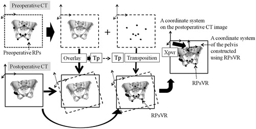
In the computer matching method (VR), each of preoperative pelvic and femoral 3D models with preoperative RPs on a preoperative CT image were matched to a corresponding 3D bone model on a postoperative CT by the volume registration method using image-editing software (Virtual Place, AZE Ltd., Tokyo, Japan) after manual trimming of unrelated lesions from preoperative and postoperative CT images wherever possible, using the image-editing software to maximize the accuracy of volume registration.[Citation23,Citation24] As a result, the rotation and translation of preoperative CT coordinate system during each matching process was recorded as an affine matrix (Tp, pelvic matrix; Tf, femoral matrix). Therefore, coordinates for preoperative RPs in the bone model of the preoperative CT coordinate system can be converted to postoperative RPs (RPsVR) in the bone model of the postoperative CT coordinate system by calculating Tp and Tf. It has been reported elsewhere that the mean translation and rotation error for VR were 0.7 mm and 0.8° for the pelvis and 0.2 mm and 1.2° for the femur.[Citation23] Therefore, preoperative RPs and pelvic and femoral coordinate systems were transferred into postoperative CT images as postoperative RPs (RPsVR), and pelvic and femoral coordinate systems, whose affine matrices in the postoperative CT coordinate system were defined as Xpvr and Xfvr, were determined with high accuracy by VR ().
First, we calculated the absolute distance between corresponding points in RPsVR and RPsM1 and in RPsVR and RPsM2 to evaluate which points were difficult to reproduce reliably. Second, we performed simulations to understand the clinical influence of discrepancies between postoperative coordinate systems created using VR and those constructed using M1 or M2 on postoperative evaluation of implant orientation ().
Figure 4. A simulation to study the influence of discrepancies between postoperative coordinate systems for the pelvis and femur created using the computer matching method (VR) and those constructed using the first or second manual methods (M1 or M2) on postoperative evaluation of implant orientations. These examples are for a cup simulation. Here, a virtual cup has been set at 40°of radiographic inclination and 15° of radiographic anteversion to the postoperative pelvic coordinate system constructed by VR, which defined matrix Xpvr in the coordinate system for the postoperative CT image. We calculated cup orientation when the virtual cup was viewed from the postoperative pelvic coordinate system constructed by M1 or M2, which defined matrix Xpm1 or Xpm2, respectively.
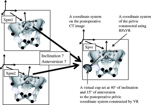
For the pelvis, we investigated absolute deviation in cup orientation when a cup set at a radiographic inclination of 40° and anteversion 15° to the postoperative pelvic coordinate system constructed by VR (Xpvr) on the postoperative CT image was compared with the postoperative pelvic coordinate system created by M1 or M2 (Xpm1 or Xpm2) on the postoperative CT image.
Radiographic cup inclination to the pelvic coordinate system created by M1 or M2 was calculated as
Radiographic cup anteversion to the pelvic coordinate system created by M1 or M2 was calculated as
where VcVR is a normal unit vector of the opening plane of the cup set at a radiographic inclination 40° and anteversion 15° in the pelvic coordinate system constructed by VR, and VcM1,M2 is a normal unit vector of the opening plane of the cup in the pelvic coordinate system constructed by M1 or M2.
For the femur, we investigated absolute deviation in stem anteversion when a stem with a 127° neck-shaft angle was set in 30° of anteversion and at neutral varus–valgus and flexion–extension angles to the postoperative femoral coordinate system constructed by VR (Xfvr) on the postoperative CT image was compared with the postoperative femoral coordinate system created by M1 or M2 (Xfm1 or Xfm2) on the postoperative CT image.
The unit neck vector of the stem was set at a 127° neck-shaft angle and 30° of anteversion in the coordinate system constructed by VR (in the case of the right femur):
Stem anteversion to the femur coordinate system created by M1 or M2 was calculated as
where VsVR is a unit vector of the neck set at anteversion 30° in the coordinate system constructed by VR, and VsM1,M2 is a unit vector of the neck in the coordinate system constructed by M1 or M2.
We analyzed statistics by performing a paired t-test and an F test. p Values of < 0.05 were considered statistically significant.
Finally, although all planning and evaluation was performed by one observer who was not the surgeon, we also investigated intraobserver and interobserver error using intraclass correlation coefficients (ICCs) for constructing postoperative RPs by M1 and M2. To evaluate intraobserver error for M1 and M2, one observer chose a set of RPs (eight RPs in the pelvis and six RPs in the femur) twice using M1 and M2 for 20 sets of RPs in 20 patients, and then compared the first and second coordinates for each method. To assess interobserver error for M1 and M2, two observers chose a set of RPs once for 20 sets of RPs in 20 patients, and then compared the first and second coordinates for each method. The ICC was calculated for each coordinate of RPs.
Results
Postoperative coordinates of RPs
In the pelvis, the deviation of total RPsM1 and RPsM2 from RPsVR was 7.8 ± 11.7 mm and 2.3 ± 1.5 mm (mean ± SD), respectively. In the femur, the respective deviation was 6.1 ± 5.5 and 4.2 ± 2.7 mm. The deviation of total RPM1 from RPsVR was significantly larger than that of total RPsM2 for both the pelvis and femur (p < 0.001; ).
Table 1. Deviation of RPsM1 and RPsM2 from RPsVR.
For the pelvis, the RP deviation using M1 was larger than that when using M2 at six of eight points, which were all RPs except for the LASI and RASI. For the femur, the RP deviation using M1 was larger than that when using M2 at four of six points, which were all RPs except for the bilateral MFC and LFC ().
Influence on postoperative implant orientation
The results of acetabular cup and femoral stem analysis are shown in . Errors in cup inclination using M1 and M2 were 0.7° ± 0.5° (range, 0.0–1.7°) and 0.5° ± 0.3° (range, 0.1–1.1°), respectively; errors in cup anteversion using M1 and M2 were 1.3 ± 1.2° (range, 0.1–3.6°) and 0.5° ± 0.4° (range, 0.0–1.3°), respectively. Thus, there was a significant difference between M1 and M2 regarding both inclination and anteversion errors for cups (p < 0.05), although clinically, the difference in cup inclination might be considered small. Errors in stem anteversion using M1 and M2 were 2.4° ± 2.0° (range, 0.3–7.6°) and 2.7° ± 2.1° (0.2–8.7°), respectively, which was not a significant difference.
Table 2. The influence of construction method for the postoperative bony coordinate system on cup and stem orientation.
The reproducibility of first and second manual methods
The mean intraobserver error and mean interobserver error were 2.3 ± 3.0 and 5.1 ± 5.2 mm, respectively, for M1 and 1.7 ± 1.0 and 3.0 ± 2.2 mm, respectively, for M2. The ICCs for intraobserver error regarding M1 and M2 were >0.97 at all RP coordinates, whereas the ICCs for interobserver error were <0.83 at all coordinates.
Discussion
Many investigators have evaluated the clinical accuracy (deviation of implant orientation from preoperative planning to postoperative measurement) and measurement error (deviation of orientation from intraoperative final measurement by navigation system to postoperative measurement) of navigation systems [Citation18,Citation21,Citation24–28]. Although a CT-based 3D templating technique is generally used for postoperative implant measurement, those results included errors in the evaluation methods, of course. Therefore, it is very important to know how accurate the evaluation method is.
The CT-based templating method has two steps. The first step involves manual reconstruction of the pelvic and femoral coordinate systems on postoperative CT images in positions as similar as possible to those used in preoperative planning. The second step involves manually overlaying 3D CAD models of implants on the real implant shadow in postoperative CT images. Then, implant orientation can be measured against the reconstructed bony coordinate system.
We first investigated the influence of manual methods (M1 and M2) for constructing postoperative pelvic and femoral coordinate systems (the first step just mentioned) on the results of postoperative evaluation of implant orientation. M2 was more accurate than M1 for postoperative evaluation of acetabular cups. However, even though for femoral stem anteversion the difference in errors between M1 and M2 was not statistically significant, both methods produced errors too large to make them useful as evaluation tools. Indeed, the difference in evaluation error between cups and stems might have affected the results of past studies. Although a few reports described clinical accuracy or measurement error in CT-based navigation systems with regard to both cups and stems, they commonly showed that results for stems were not better than those for cups.[Citation18,Citation29] Kitada et al.[Citation18] evaluated anatomic orientation of cup and stem anteversion in THA with a CT-based navigation system, just as we did. They reported that the navigation system produced a measurement error of 0.4° ± 2.5° (range, −6° to 5°) for cup inclination, −0.8° ± 4.1° (range, −6° to 8°) for cup anteversion, and –0.6° ± 4.8° (range, –11° to 10°) for stem anteversion, which is noteworthy because cup inclination and anteversion in anatomic notation are larger than those in radiographic notation. Similarly, another group of investigators revealed that the clinical accuracy of stem anteversion was worse than that of cup anteversion in THA with same navigation system.[Citation29] They investigated the influence of the thickness of CT slices, but they found no effect on stem anteversion when slices were between 1 and 3 mm thick.
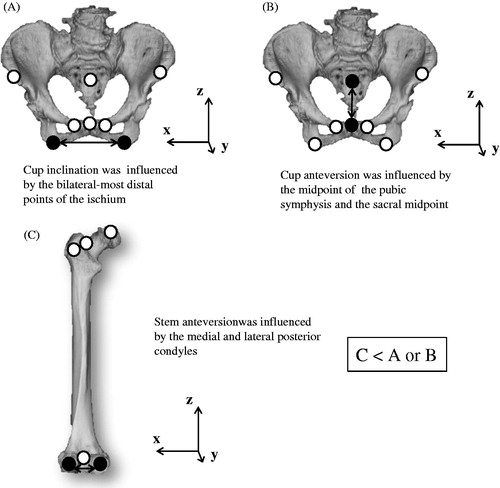
We suspect that the reason errors in stem orientation were much larger than errors in cup orientation originates from the difference in distance between two RPs that defined a coordinate system axis. Cup inclination and anteversion are theoretically influenced by the tilt of the horizontal axis and anteroposterior axis, respectively, of the pelvic coordinate system. Those are determined by the LIS and RIS and by the PUB and sacral midpoint, respectively. For the pelvis, the amounts of deviation of RPsM1 and RPsM2 from RPsVR were very different (7.8 ± 11.7 and 2.3 ± 1.5 mm, respectively), and the deviation was especially large in those RPs determined by M1. We believe that these might cause a difference in accuracy of cup orientation between M1 and M2. Meanwhile, although the amounts of deviation of RPsM1 and RPsM2 from RPsVR in the femur (6.0 ± 5.5 and 4.3 ± 2.7 mm, respectively) were not as large as those in the pelvis, accuracy of measurement of stem anteversion was worse. Stem anteversion is strongly influenced by the tilt of the horizontal axis of the femur, which is mainly determined by the posterior-most points of the MFC and LFC. Because the distance between the RPs on the femur is commonly shorter than of the distance between pelvic RPs, which influenced cup position, stem anteversion may likely be influenced more than cup inclination and anteversion because of positioning error for those RPs, even if error is not as large ().
Figure 5. RPs that can theoretically influence (A) cup inclination, (B) cup anteversion, and (C) stem anteversion (black circles).
Our study had some limitations. First, we set the gold-standard RPs on postoperative bone models by using the computer-matching technique; therefore, strictly speaking, we did not verify whether the gold-standard RPs were accurate. For verification, cadaver studies are necessary. However, ours was a clinical study. Therefore, we used postoperative RPs converted by VR, which is known to be highly accurate. Although our results included a registration error inherent in this method, we believe that it did not affect our conclusion.
Second, we investigated the influence of only the first step in the 3D templating technique on the measurement implant orientation. In the clinical setting, the error originates from the second step when overlaying a 3D CAD model on the real implant shadow, and this may add to the error from the first step. Therefore, we speculate that the accuracy of this method may be a little worse than our findings indicate. The measurement error for the CT-based navigation system was experimentally confirmed to be <1 mm and 1°.[Citation30] Therefore, manual reconstruction of the postoperative coordinate system is insufficient for the first step in the postoperative evaluation method, at least for the femur. It will be necessary to develop an easier technique that is as accurate as VR.
Third, we simulated only one of the best situations for cup and stem alignment or design, so that we could investigate the influence of deviation of the coordinate system reconstructed by two different methods on the measurement of implant orientation. Therefore, if a different postoperative implant orientation is evaluated, it is possible that the results will differ, so further research is necessary to determine the influence of these factors.
Fourth, one examiner chose RPs to construct both preoperative and postoperative coordinate systems of 3D bone models from CT images. Intraobserver error was less than interobserver error for both M1 and M2. Therefore, accuracy may be worse when two different examiners conduct planning and postoperative assessment than it is when same person performs both evaluations.
Conclusion
We investigated the influence of two manual methods for reconstruction of the postoperative pelvic and femoral coordinate systems on the findings regarding implant orientations after THA as assessed on CT images. M2 appears to be accurate for postoperative evaluation of acetabular cup orientation. We recommend referring to preoperative RPs when choosing postoperative RPs. Surgeons must be aware that for evaluation of postoperative stem anteversion, manual methods may produce considerable error.
Declaration of interest
The authors report no declarations of interest.
Acknowledgements
Medical editor Katharine O'Moore-Klopf, ELS (East Setauket, NY, USA) provided professional English-language editing of this article.
References
- Iida H, Kaneda E, Takada H, et al. Metallosis due to impingement between the socket and the femoral neck in a metal-on-metal bearing total hip prosthesis. A case report. J Bone Joint Surg Am 1999;81:400–403.
- Gambera D, Carta S, Crainz E, et al. Metallosis due to impingement between the socket and the femoral head in a total hip prosthesis. A case report. Acta Biomed 2002;73:85–91.
- Barrack RL. Dislocation after total hip arthroplasty: implant design and orientation. J Am Acad Orthop Surg 2003;11:89–99.
- Bader R, Steinhauser E, Zimmermann S, et al. Differences between the wear couples metal-on-polyethylene and ceramic-on-ceramic in the stability against dislocation of total hip replacement. J Mater Sci Mater Med 2004;15:711–718.
- Shon WY, Baldini T, Peterson MG, et al. Impingement in total hip arthroplasty a study of retrieved acetabular components. J Arthroplasty 2005;20:427–435.
- Grammatopoulos G, Pandit H, Glyn-Jones S, et al. Optimal acetabular orientation for hip resurfacing. J Bone Joint Surg Br 2010;92:1072–1078.
- Widmer KH, Zurfluh B. Compliant positioning of total hip components for optimal range of motion. J Orthop Res 2004;22:815–821.
- Sugano N, Nishii T, Miki H, et al. Mid-term results of cementless total hip replacement using a ceramic-on-ceramic bearing with and without computer navigation. J Bone Joint Surg Br 2007;89:455–460.
- Sugano N, Takao M, Sakai T, et al. Does CT-based navigation improve the long-term survival in ceramic-on-ceramic THA? Clin Orthop Relat Res 2012;470:3054–3059.
- DiGioia AM, Jaramaz B, Blackwell M, et al. The Otto Aufranc Award. Image guided navigation system to measure intraoperatively acetabular implant alignment. Clin Orthop Relat Res 1998;355:8–22.
- Nogler M, Kessler O, Prassl A, et al. Reduced variability of acetabular cup positioning with use of an imageless navigation system. Clin Orthop Relat Res 2004;426:159–163.
- Radermacher K, Portheine F, Anton M, et al. Computer assisted orthopaedic surgery with image based individual templates. Clin Orthop Relat Res 1998;354:28–38.
- Hananouchi T, Saito M, Koyama T, et al. Tailor-made surgical guide reduces incidence of outliers of cup placement. Clin Orthop Relat Res 2010;468:1088–1095.
- Sugano N. Computer-assisted orthopaedic surgery and robotic surgery in total hip arthroplasty. Clin Orthop Surg 2013;5:1–9.
- Ghelman B, Kepler CK, Lyman S, Della Valle AG. CT outperforms radiography for determination of acetabular cup version after THA. Clin Orthop Relat Res 2009;467:2362–2370.
- Lin F, Lim D, Wixson RL, et al. Validation of a computer navigation system and a CT method for determination of the orientation of implanted acetabular cup in total hip arthroplasty: a cadaver study. Clin Biomech (Bristol, Avon) 2008;23:1004–1011.
- Kalteis T, Handel M, Herold T, et al. Position of the acetabular cup—accuracy of radiographic calculation compared to CT-based measurement. Eur J Radiol 2006;58:294–300.
- Kitada M, Nakamura N, Iwana D, et al. Evaluation of the accuracy of computed tomography-based navigation for femoral stem orientation and leg length discrepancy. J Arthroplasty 2011;26:674–679.
- Beaumont E, Beaumont P, Odermat D, et al. Clinical validation of computer-assisted navigation in total hip arthroplasty. Adv Orthop 2011;2011:171783.
- Hasart O, Poepplau BM, Asbach P, et al. Ultrasound-based navigation and 3D CT compared in acetabular cup position. Orthopedics 2009;32:6–10.
- Kim TH, Lee SH, Yang JH, Oh KJ. Computed tomography assessment of image-free navigation-assisted cup placement in THA in an Asian population. Orthopedics 2012;35:13–17.
- Sugano N, Tsuda K, Miki H, et al. Dynamic measurements of hip movement in deep bending activities after total hip arthroplasty using a 4-dimensional motion analysis system. J Arthroplasty 2012; 27:1562–1568.
- Watanabe Y, Matsumoto J, Sasama T, et al. Preprocessing method for rigid registration between pre- and postoperative CT images in total hip replacement. Med Imag Technol 2003;21:358–368 [in Japanese].
- Iwana D, Nakamura N, Miki H, et al. Accuracy of angle and position of the cup using computed tomography-based navigation systems in total hip arthroplasty. Comput Aided Surg 2013;18:187–194.
- Ryan JA, Jamali AA, Bargar WL. Accuracy of computer navigation for acetabular component placement in THA. Clin Orthop Relat Res 2010;468:169–177.
- Hayashi S, Nishiyama T, Fujishiro T, et al. Evaluation of the accuracy of femoral component orientation by the CT-based fluoro-matched navigation system. Int Orthop 2013;37:1063–1068.
- Fukunishi S, Fukui T, Imamura F, Nishio S. Assessment of accuracy of acetabular cup orientation in CT-free navigated total hip arthroplasty. Orthopedics 2008;31.
- Ybinger T, Kumpan W, Hoffart HE, et al. Accuracy of navigation-assisted acetabular component positioning studied by computed tomography measurements: methods and results. J Arthroplasty 2007;22:812–817.
- Hirasawa N, Matsubara M, Ishii K, et al. Effect of CT slice thickness on accuracy of implant positioning in navigated total hip arthroplasty. Comput Aided Surg 2010;15:83–89.
- Sugano N, Sasama T, Sato Y, et al. Accuracy evaluation of surface-based registration methods in a computer navigation system for hip surgery performed through a posterolateral approach. Comput Aided Surg 2001;6: 195–203.