Abstract
This review will first recall the phenomena of “cortical inheritance” observed and genetically demonstrated in Paramecium 40 years ago, and later in other ciliates (Tetrahymena, Oxytricha, Paraurostyla), and will analyze the deduced concept of “cytotaxis” or “structural memory”. The significance of these phenomena, all related (but not strictly restricted ) to the properties of ciliary basal bodies and their mode of duplication, will be interpreted in the light of present knowledge on the mechanism and control of basal body/centriole duplication. Then other phenomena described in a variety of organisms will be analyzed or mentioned which show the relevance of the concept of cytotaxis or structural memory to other cellular processes, mainly (1) cytoskeleton assembly and organization with examples on ciliates, trypanosome, mammalian cells and plants, and (2) transmission of polarities with examples on yeast, trypanosome and metazoa. Finally, I will discuss some aspects of this particular type of non DNA inheritance: (1) why so few documented examples if structural memory is a basic parameter in cell heredity, and (2) how are these phenomena (which all rely on protein/protein interactions, and imply a formatting role of preexisting proteinic complexes on neo formed proteins and their assembly) related to prions?
Note
This manuscript has been previously published: Centriole Wilson P. Chernoff Y. Inheritance. Protein-Based Inheritance 2007; Austin and New York Landes Bioscience and Kluwer Academic Press 106 - 118
Figures and Tables
Figure 1 Cortical organization of Paramecium. The figure shows the ventral (left) and dorsal (right) sides of a cell immunolabeled by an anti-tubulin antibody which reveals basal bodies as discrete dots (bb) and an antibody directed against the ciliary rootlets (cr) which form a thin bundle emanating from each basal body, as shown in the enlargement. A-P marks the antero-posterior cell axis. The ventral side is marked by a line of contrast in the global arrangement of basal body rows, the oral meridian, which defines the right (R) and the left (L) of the cell. The oral apparatus (oa)-a ciliated funnel at the bottom of which phagocytosis takes place-and the cytoproct (cy) open on the ventral side, while the pores of the contractile vacuole systems (cvp) localize on the dorsal surface. Bar: 10 mm. Images appear courtesy of F. Ruiz.
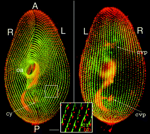
Figure 2 Morphogenetic processes during division. The figure shows interphase and dividing living cells expressing GFP-PtCen2a, a centrin specific to basal bodies.Citation29 Smaller dots correspond to a single basal body per cortical unit, larger ones to two basal bodies per unit. In the dividing cell, where basal body duplication proceeds, the division furrow (df) delimits the two presumptive daughter cells. The old oral apparatus is conserved in the anterior daughter cell, while a new one has developed in the posterior one. The two insets pinpoint three units with 2 bbs in the interphase cell and their progeny in the dividing cell. Images are shown with reverse contrast. Bar: 10 mm. Images appear courtesy of F. Ruiz.
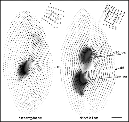
Figure 3 Basal body duplication. (A) Polarity of basal body duplication in Paramecium. Each new basal body (new bb), develops at right angles and anterior to its mother (old bb), then tilts up to become inserted in the cortex, along the same basal body row as the mother organelle.Citation4 Fibrous links connect mother and daughter basal bodies. (B) Basal body duplication in situ. This electron microscopic view of basal body duplication shows two old bbs in cross-section and two new bbs (thick arrows), still in orthogonal position, anterior to the old bbs and aligned along the row. The A-P and R-L polarities of the rows are indicated: these polarities are indicated by the position and orientation of two basal body appendages, the ciliary rootlets (thin arrows) and a microtubule ribbon (arrowheads). Bar: 100 nm. Image: courtesy of N. Garreau de Loubresse. (C) The assembly line. The scheme takes into account recent data on the molecular dissection of basal body/centriole assembly in C. elegans, Drosophila and human cells and depicts the likely general stepwise scaffolding process leading to assembly of a centriole/basal body. The earliest detectable seed is a “central tube”, forming the axis of the cartwheel corresponding to the onset of the ninefold symmetry. Then at the apex of the 9 radii, the sequential assembly and elongation of microtubule will result in the final cylinder of microtubule triplets. The same sequence is likely to take place in both templated and de novo pathway.Citation20–Citation23,Citation25,Citation26 A central tube appears as the first identified seed of the organelle; the 9-branched star symbolizes the required prepattern for the characteristic ninefold symmetry of the microtubule cylinder which elongates along with the sequential addition of tubules A–C.
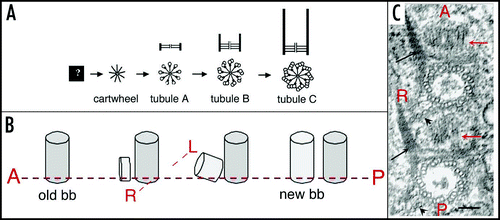
Figure 4 Duplication of the cortical pattern. (A) The elementary cortical unit. The scheme shows a basal body and its main cytoskeletal appendages whose extension defines the cortical unit. The striated ciliary rootlet (cr) runs anterior and to the right of the basal body and of the cell; the transverse microtubule ribbon (tmr) and the post-ciliary microtubule ribbon (p-cmr) run to the left and the posterior sides of the basal body respectively. (B) Duplication of the cortical units. Two adjacent units along two parallel rows are represented. Solid lines correspond to old bb and appendages, dotted lines to new organelles. Elongation of the longitudinal rows proceeds through elongation of the preexisting units and intercalation of new bbs.
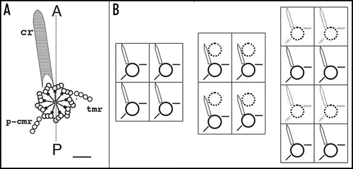
Figure 5 Organization of Paramecium doublet cells. The upper drawings outline a singlet and a homopolar doublet. In the singlet, the oral apparatus (oa) faces the observer and contractile vacuole pores (cvp) are on the hidden face. In the doublet, the second oral apparatus (oa2) is on the hidden side, while the corresponding contractile vacuole pores (cvp2) face the observer. The lower drawings represent the corresponding equatorial cross-sections, allowing a better visualization of the tandem organization of the doublet. R, L, V, D mark right, left, ventral, and dorsal sides of the singlet, respectively; R1/R2, V1/V2, etc. localize the different fields of the fused cells in the doublet.
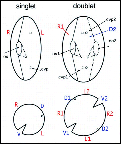
Figure 6 Visualization of an inverted ciliary row. As in , double staining of basal bodies and ciliary rootlets indicates the polarity of basal bodies and cortical units. On the left panel, the arrow points to a discontinuity in the cortical pattern. On the right panel, the enlargement around this discontinuity shows the direction of the ciliary rootlets, which run downward and to the right of the observer in the case of the inverted row, while they run upward and to the left of the observer for normally oriented rows. Bar: 10 mm. Image appears courtesy of F. Ruiz.
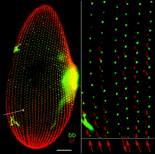
Figure 7 Organization of the infraciliary lattice. This cytoskeletal network is composed of centrins and centrin-binding proteins associated in bundles of microfilaments. The lattice is labeled by anti-centrin antibodies (in green). (A) In a wild type cell, the ICL network subtends the whole cell and each mesh encircles a basal body (labeled in red by an anti-tubulin antibody). (B) In cells depleted of one of the constitutive centrins by RNAi treatment, the network is disassembled, but cortical units retain dots of anti-centrin reactive material flanking the basal bodies. Bar: 10 mm.
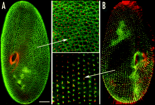
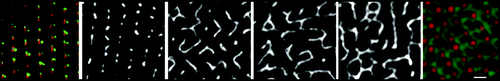
Figure 8 Mode of reassembly of the infraciliary lattice. Upon release of the silencing conditions, filaments arise from the residual dots flanking the basal body. The four images in black end white show, from left to right, the progress of reassembly over 1–3 divisions; and the network does not recover its normal pattern (rightmost image) until 10–15 divisions. Bar: 2 mm.