Abstract
We previously showed that over production of a fusion protein in which the prion domain of Saccharomyces cerevisiae [PSI+] is connected to glutathione S-transferase (GST-Sup35NM) causes a marked decrease in the colony forming ability of Escherichia coli strain BL21 after reaching stationary phase. Evidence indicated that the observed toxicity was attributable to intracellular formation of fibrous aggregates of GST-Sup35NM. In this report, we describe the isolation of plasmids that encode mutant forms of GST-Sup35NM which do not confer the toxicity to E. coli strain BL21. Each of the four spontaneous mutant-forms of GST-Sup35NM obtained revealed amino acid substitutions. One substitution was located in the N domain, and the others in the M domain. Congo red binding assay indicated that none of these mutant protein underwent conformational alteration in vitro. From these results, we conclude that the M domain, in collaboration with the N domain, plays an essential role in aggregation of Sup35NM. In addition, our data demonstrate the usefulness of the E. coli expression system in studying aggregate-forming proteins.
Acknowledgements
This work was supported by funds from the Bio-Venture project and the 21st century COE program of Ritsumeikan University. HK was supported by the Frontier financial program of Ritsumeikan University.
Figures and Tables
Figure 1 Detection of mutants that did not exhibit rapid decrease of colony forming ability in the stationary phase. (A) E. coli strain BL21 was transformed with pGEX-SUP35NM, and colony forming ability was examined as described in Materials and Methods. In a majority of cases colony forming ability decreased quickly (solid line), but there were cases (at a frequency of about a 5% of the trials) in which the colony forming ability temporarily increased; of a total of eight such cases, three are shown in this figure (dotted lines). (B) From each of the eight exceptional cases, a representative clone was picked, inoculated in fresh growth medium, and examined for colony forming ability as before; only the three clones corresponding to the exceptional cases shown in are shown.
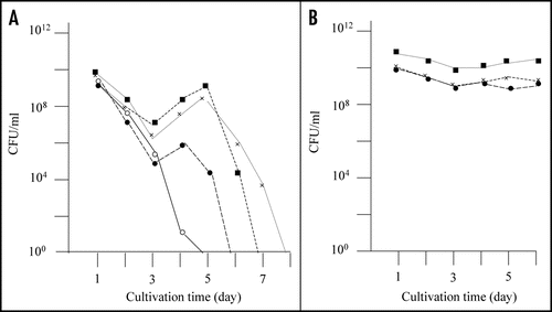
Figure 2 Nontoxic effects of the recovered plasmids against E. coli strain BL21. Colony forming ability of E. coli strain BL21 transformed with the recovered plasmids was examined; the results of three plasmids out of the eight recovered plasmids are included in this figure (solid marks). Colony forming ability of E. coli strain BL21 transformed with pGEX-SUP35NM is shown for comparison (open circle).
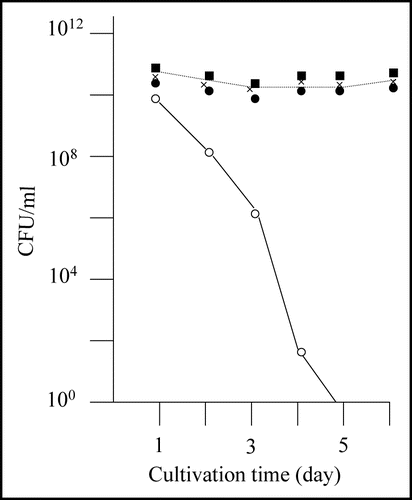
Figure 3 SDS-PAGE profiles of the eight spontaneous mutants obtained. Cell extract from each of the eight mutants of interest (M-1 through M-8) was prepared and subjected to SDS-PAGE as described in Materials and Methods. C and G represent control BL21/pGEX-SUP35NM (producing GST-Sup35NM) and BL21/pGEX-4T-3 (producing GST), respectively. SM1 and SM2 are two different mixtures of size markers. A band corresponding to a position of 55 kDa is marked with open or solid arrow head; for explanation, see text.
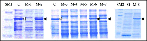
Figure 4 Congo red binding assay. The results of Congo red binding assay of the mutants, M-2 (▲),M-6 (●), M-7 (▽) and M-8 (■). The result of BL21/pGEX-SUP35NM (◯) is shown for comparison. For experimental details, see Materials and Methods.
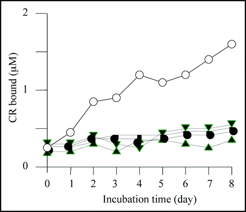
Figure 5 Base substitutions detected in plasmid recovered from mutants. For each mutant, only the portion of relevant comparative SUP35NM sequence is shown. Numbers indicate base positions in SUP35NM. Letters below corresponding vertical arrows represent bases that were observed in the mutants.
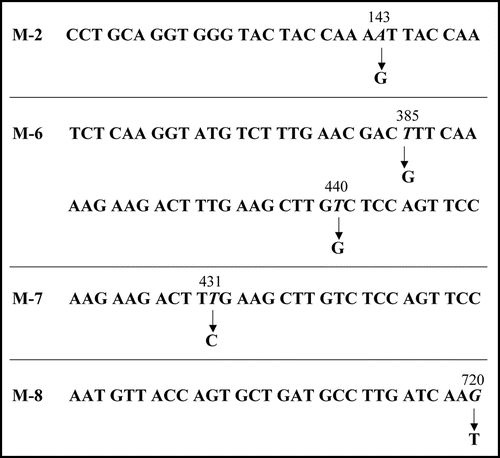
Figure 6 Amino acid replacement expected from detected base substitutions. Boxes represent the N and M domains of Sup35NM, and numbers below the boxes indicate amino acid positions in Sup35NM.
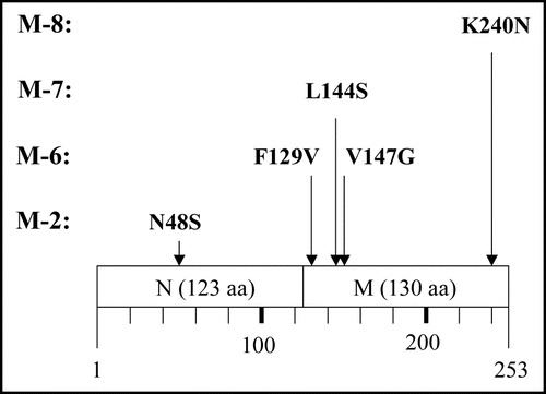
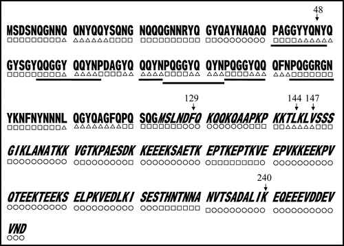
Figure 7 Predicted secondary structures of Sup35NM. Gothic and italic letters indicate amino acids in the N and M domains of Sup35, respectively; underscores indicate six times repeat of PQGGYQQYN present in the N domain of Sup35. Secondary structures within Sup35NM predicted by the method of Chou and Fasman (1978) are notated below the corresponding amino acid sequence; circle, square and triangle represent amino acids composing α helix, β Sheet and coil, respectively. Numbers indicate positions where amino acid replacements were determined in the present study.