Figures & data
Fig. 7a Test set-up.
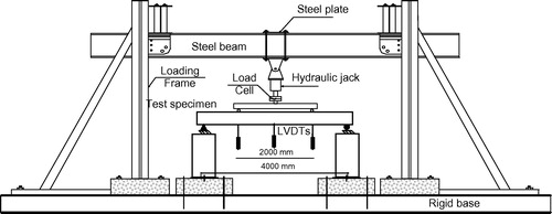
Fig. 7b Test set-up of beam specimens.
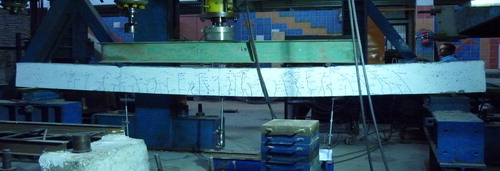
Fig. 1 Concrete dimensions and cable profile of prestressed beams.
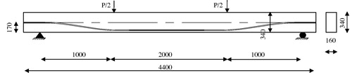
Fig. 3 The prestressing strand placed inside the polyethylene duct.
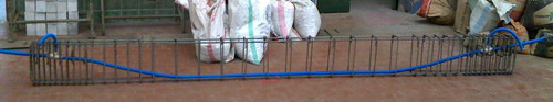
Fig. 4 Application of the prestressing force.
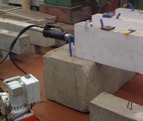
Fig. 5 Grouting process.
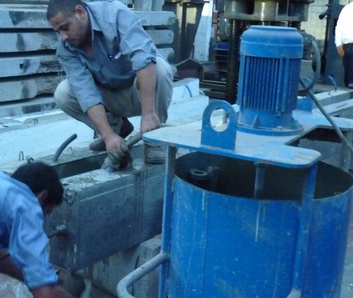
Table 1 Experimental program for beams.
Fig. 6 The calculated and measured prestressing stress along the beam span for Partially prestressed beam with compressive strength 72 MPa.
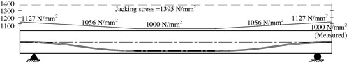
Fig. 2a Reinforcement details of non-prestressed beams.
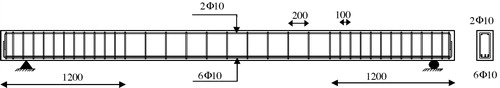
Fig. 2b Reinforcement details of fully prestressed beams.
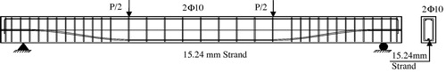
Fig. 2c Reinforcement details of partially prestressed beams.
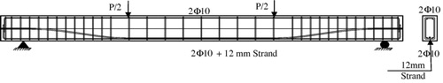
Fig. 8 Cyclic loading pattern.
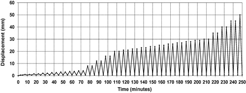
Fig. 9 Location of the different instrumentations.
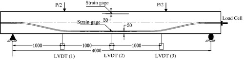
Table 2 Experimental results.
Table 3 Ductility index.
Fig. 10 Failure modes of tested specimens.
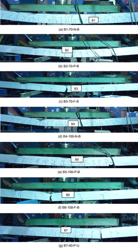
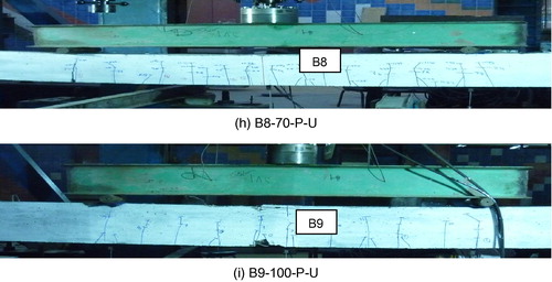
Fig. 11 Load deflection relationship for specimens B1-70-N-B, B2-70-P-B and B3-70-F-B.
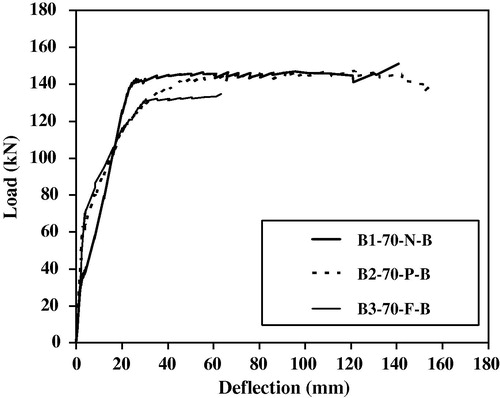
Fig. 12 Load deflection relationship for specimens B4-100-N-B, B5-100-P-B and B6-100-F-B.
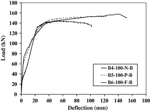
Fig. 13 Load deflection relationship for specimens B2-70-P-B and B8-70-P-U.
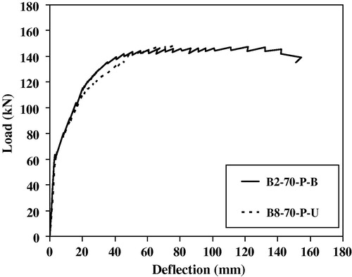
Fig. 14 Load deflection relationship for specimens B5-100-P-B and B9-100-P-U.
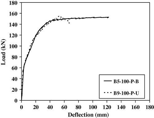
Fig. 15 Load deflection relationship for specimens B1-70-N-B and B4-100-N-B.
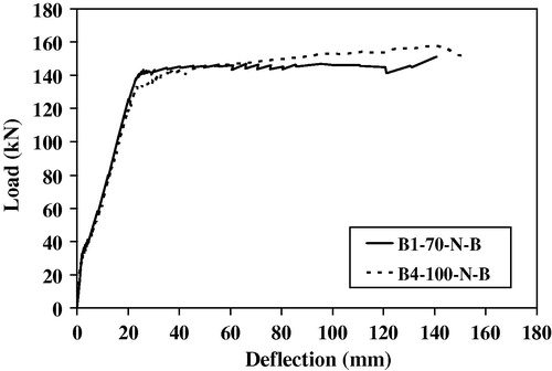
Fig. 16 Load deflection relationship for specimens B2-70-P-B and B5-100-P-B.
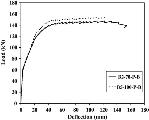
Fig. 17 Load deflection relationship for specimens B3-70-F-B and B6-100-F-B.
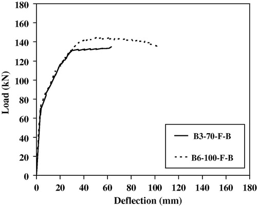
Fig. 18 Load deflection relationship for specimens B7-40-P-U, B8-70-P-U and B9-100-P-U.
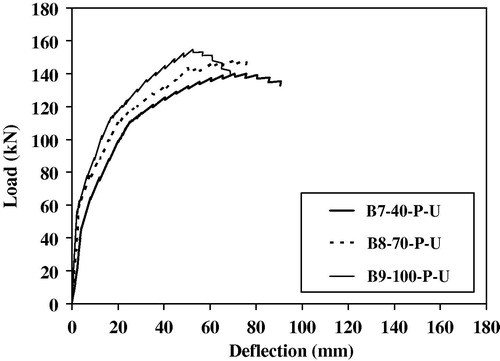
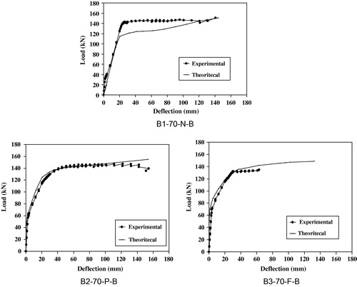
Fig. 19 The measured and predicated load-deflection curves of tested beams.
Table