Figures & data
Fig. 1 (a) Fully composite section, (b) interfacial shear transfer in composite section, (c) horizontal slip, (d) non-composite section.
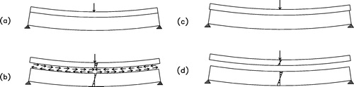
Fig. 2 Typical details of tested beams.
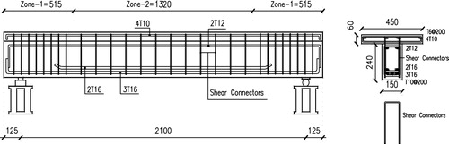
Table 1 Matrix of tested beams.
Fig. 3 Test set-up for the beams.
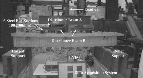
Fig. 4 Instrumentation for the beams.
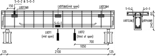
Fig. 5 Prediction of ductility.
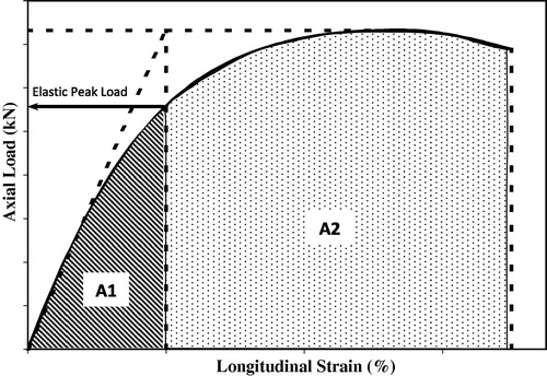
Table 2 Results of tested beams.
Fig. 6 Failure and cracking pattern for beams.
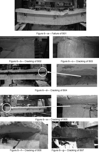
Fig. 7 (a) Load–Mid-span deflection Curves for un-retrofitted beams. (b) Horizontal shear deformation of beams.
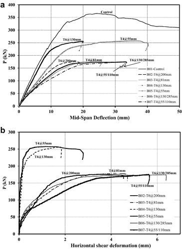
Table 3 Capacities of rectangular and flanged sections.
Fig. 8 The strut and tie mechanism for the tested beams.
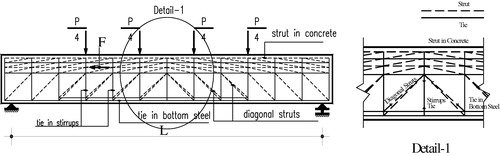
Table 4 Parameters and results from strut and tie models compared with experimental results.
Fig. 9 Proposed relationship between “α“ and horizontal shear force.
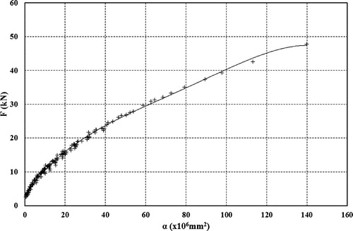
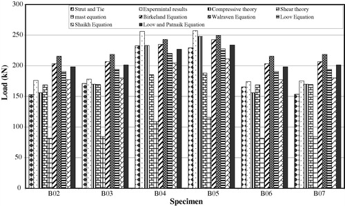
Table 5 Maximum interfacial shear from existing models and codes compared to experimental values.
Fig. 10 Results calculated from previous research and codes compared to experimental results.