Figures & data
Fig. 1 XRD patterns of 60 V2O5–5P2O5–(35 − x)B2O3–xDy2O3 for: (a) S1, (b) S2, (c) S3, (d) S4 and (e) S5.
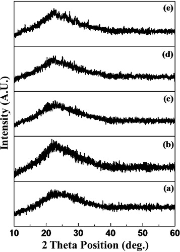
Fig. 2 UV–VIS spectrum of the 60 V2O5–5P2O5–(35 − x)B2O3–xDy2O3 glass system.
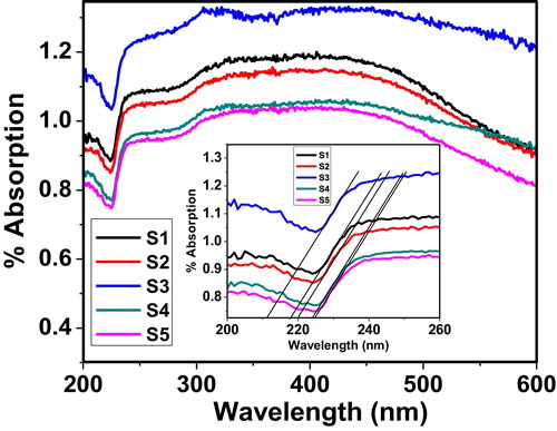
Fig. 3 Variation of the extinction coefficient of the 60 V2O5–5P2O5–(35 − x)B2O3–xDy2O3 glass system as a function of wavelength.
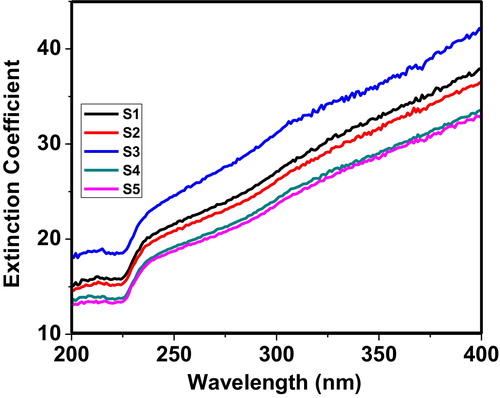
Fig. 4 Variation of refractive index of the 60 V2O5–5P2O5–(35 − x)B2O3–xDy2O3 glass system as a function of wavelength.
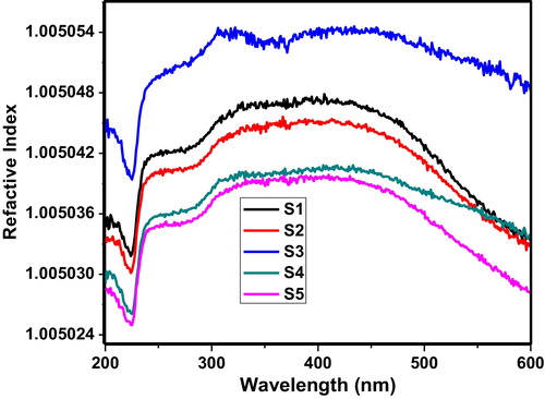
Fig. 5 Variation of optical conductivity of the 60 V2O5–5P2O5–(35 − x)B2O3–xDy2O3 glass system as a function of wavelength.
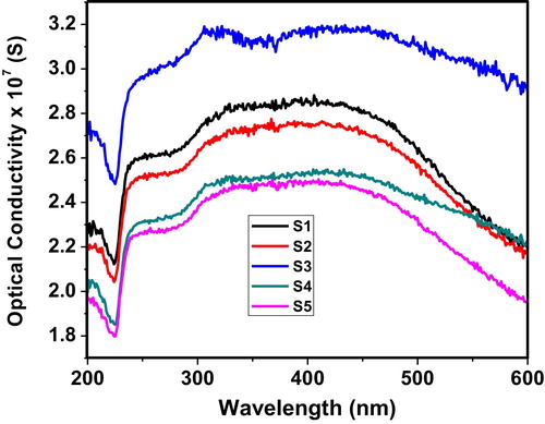
Fig. 6 Variation of the real dielectric constant of the 60 V2O5–5P2O5–(35 − x)B2O3–xDy2O3 glass system as a function of wavelength.
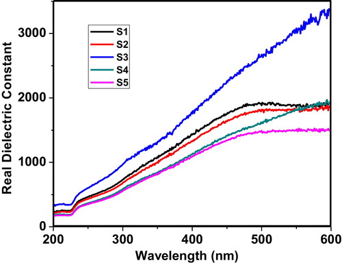
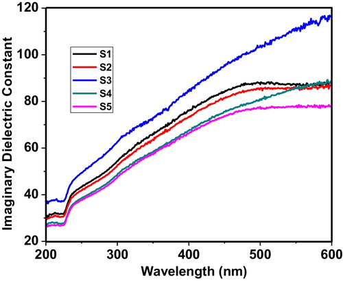
Fig. 7 Variation of the imaginary dielectric constant of the 60 V2O5–5P2O5–(35 − x)B2O3–xDy2O3 glass system as a function of wavelength.