
Figures & data
Figure 1. Positions of Dougong in historical Chinese buildings.
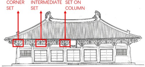
Figure 2. Dougong components and structure.
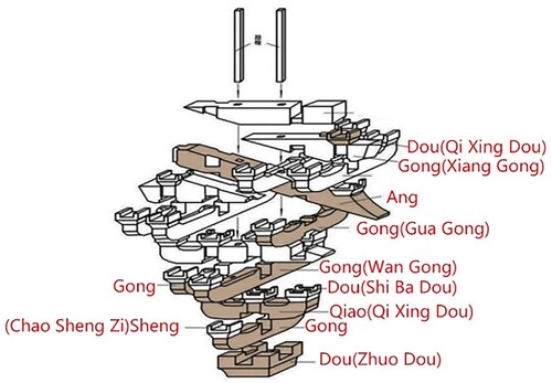
Figure 3. Flowchart of the systematic review method.
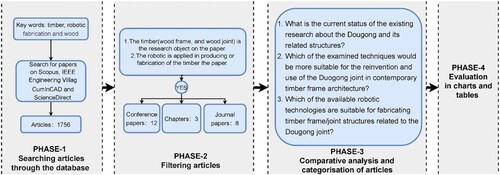
Figure 4. Distribution of articles by sources of publication (total number of articles: 23).
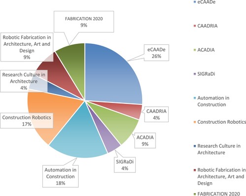
Figure 5. Geographical distribution of articles (total number of articles: 23).
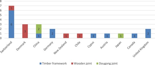
Figure 6. Chronological distribution of articles.
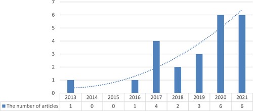
Table 1. Article categorization based on their timber structure type.
Figure 7. a) Timber arch bridge(Kunic et al. Citation2021); b) A re-configurable timber architecture (Kunic et al. Citation2021).
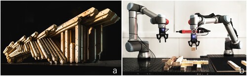
Figure 8. Six free-form timber structures, a) sizeable freeform roof (Willmann et al. Citation2016), b) free-form timber walls (Kontovourkis Citation2017), c) double-storey structure(Eversmann, Gramazio, and Kohler Citation2017), d) free-form structure designed with dowel-laminated timber(Leopold, Robeller, and Weber Citation2019), e) freeform timber structure with double-curved glulam beams (Chai, So, and Yuan Citation2021), f) douglas fir struts (Morse et al. Citation2020).
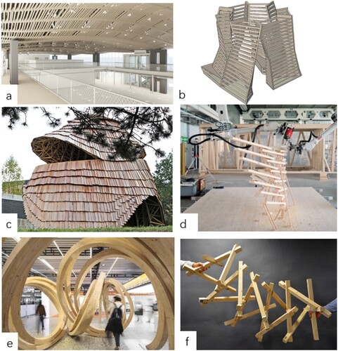
Figure 9. A robot trained to fabricate an overlap joint by Apolinarska et al. (Citation2021).
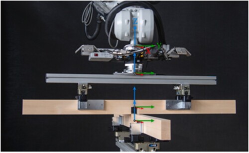
Figure 10. Free-form timber structure by Apolinarska et al. (Citation2021).
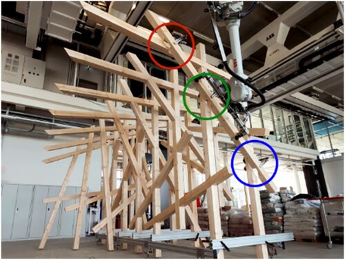
Figure 11. A freeform, reciprocal timber frame structure (Mostafavi et al. Citation2020).
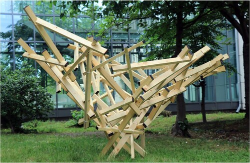
Figure 12. A timber-frame wall(Xian, Hoban, and Peters Citation2020).

Figure 13. a) Three timber explorations designed according to the Dougong, a reciprocal structure, and a rigid lock system (Lange Citation2017); b) A timber tower designed based on the connection method of the Dougong (Chai et al. Citation2019).
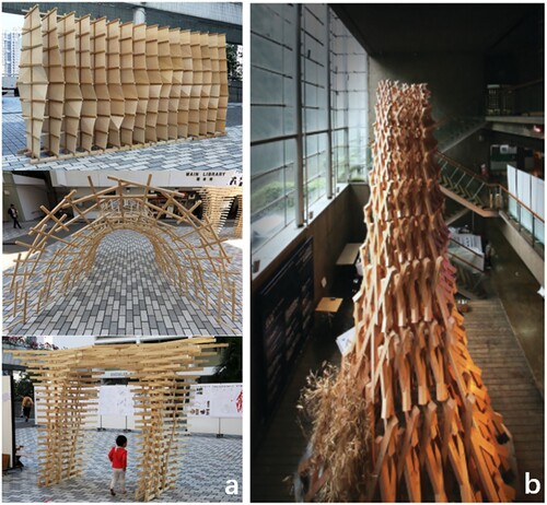
Figure 14. a) a Japanese wood joint (Dank and Freissling Citation2013), b) a part of a traditional Japanese pagoda(Takabayashi and Kado Citation2019), c) a Chidori joint (Koerner-Al-Rawi et al. Citation2020), d) a T-bridle joint, e) mortised rabbeted oblique splice(Heesterman and Sweet Citation2018).
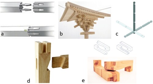
Table 2. Article categorization based on the optimization method used.
Table 3. Article categorization based on robotic end-effectors used.
Figure 15. a) a band saw end-effector, b) a spindle end-effector used to produce free-form beams (Chai, So, and Yuan Citation2021).
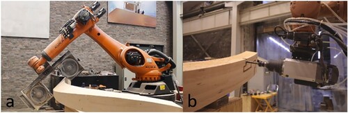
Figure 16. a) circular saw, b) square chisel, c) vibration chisel and d) router, designed by Takabayashi and Kado (Citation2019).
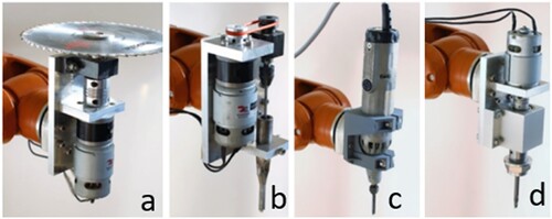
Figure 17. a) mechanical clamp and quick tool changer (Apolinarska et al. Citation2021), b) multi-functional end-effector, including a gripper, wrist switch and screwdriver(Kunic et al. Citation2021),c) end-effector with a wrist camera applied to scan beams (Kunic et al. Citation2021).
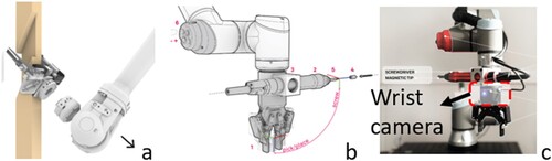
Figure 18. Proposed workflow for reinterpreting the Dougong joint.
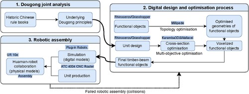
Table 4. Analysis of robotic firmware used in the selected papers.
Table 5. Human-robot cooperation types.
Figure 19. The simplification process of two the Dougong components, and the descretised components within a voxel.
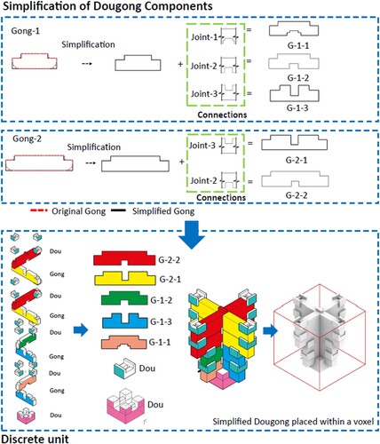
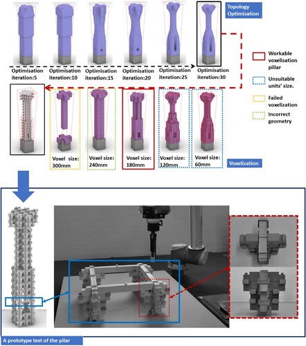
Figure 20. Optimization and voxelisation of the pillar, and the assembly of the prototype fragment of a pillar.
Data availability statement
Data sharing is not applicable to this article as no new data were created or analysed in this study.