
Figures & data
Table 1. Summary description of cooling interventions (see for images).
Figure 1. Schematic diagram of pre-determined 72.5 m route along which the stroller was pushed during each 20-min intervention. The red dashed lines indicate the stroller route, the red arrows indicate the direction, the hatched circle indicates the location of the environmental measuring unit, placed on the tarmac of the nearby parking lot unobstructed.
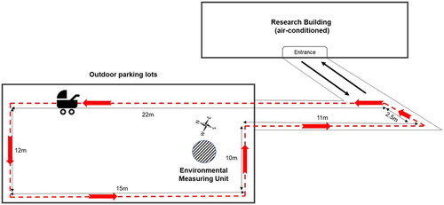
Figure 2. In-stroller thermistors and Kestrel 5400-unit placement within the purpose-built wire frame. Numbers 1–4 indicate individual thermistor placement relative to a simulated infant’s body segments (i.e. head, chest, abdomen, and legs). Numbers 5 and 6 indicate the thermistor placement measuring the temperature in the upper portion of the stroller carriage space, close to the canopy. The orange icon indicates the location of the Kestrel 5400 unit, placed near the centre of the wire frame, which was suspended 15 cm above the stroller seat surface.
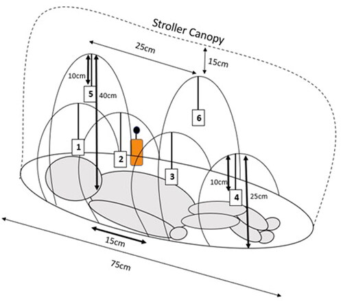
Figure 3. The tested stroller cooling interventions. All fabric drapings were secured using plastic clothes pegs, ensuring that there were no gaps present. For illustrative purposes, the drapings of interventions E and F were raised on one side to display the position of the battery-operated fan.
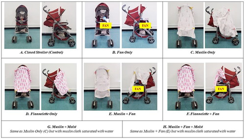
Table 2. The mean (mean of 16 separate experimental observations) end of trial in-stroller and outside ambient environmental conditions and the mean differences observed between in-stroller vs outside for each stroller configuration.
Figure 4. The mean (minute averaged data) in-stroller environmental conditions for each stroller cooling intervention. Due to the number of interventions presented, error bars have been omitted for clarity.
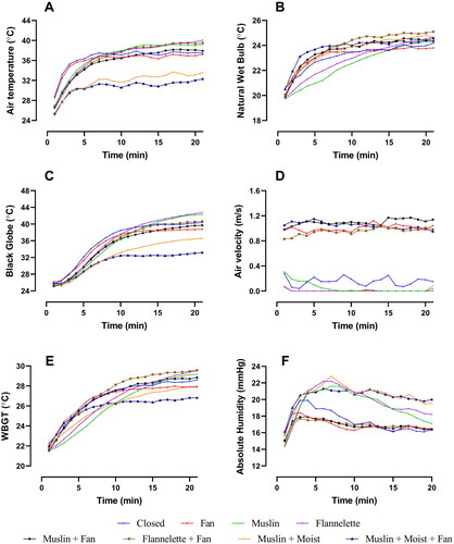
Figure 5. The mean end-trial difference between the in-stroller vs outside air temperature (Ta) and WBGT, expressed relative to the difference observed during Closed Stroller Control. T1–T6 represent the mean relative ΔTa for each of the six thermistors located in the stroller chamber.* Significantly lower than Closed Stroller Control (p < 0.05). †Significantly higher than Closed Stroller Control (p < 0.05).
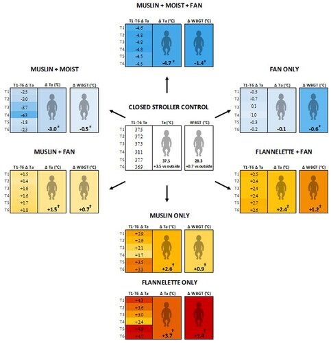
Table 3. Muslin characteristics pre- and post-trial and the evaporative cooling yielded.