1,388
Views
3
CrossRef citations to date
0
Altmetric
Original Articles

Analysis of the state of poling of lead zirconate titanate (PZT) particles in a Zn-ionomer composite

, , , , , & show all
Pages 139-150 | Accepted 25 Jun 2015, Published online: 22 Feb 2016

Figures & data

Figure 1. Experimental set up for time resolved high energy X-ray diffraction and the 2 D diffraction image shows the Debye-Scherrer rings.
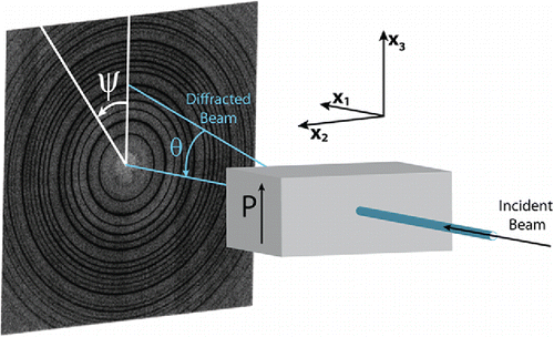
Figure 1. Experimental set up for time resolved high energy X-ray diffraction and the 2 D diffraction image shows the Debye-Scherrer rings.

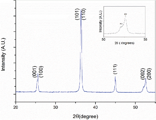
Figure 2. XRD diffraction pattern of PZT 507 powder used for fabrication of 0 3 ionomer composites.

Figure 2. XRD diffraction pattern of PZT 507 powder used for fabrication of 0 3 ionomer composites.

Figure 3. SEM micrographs PZT-ionomer composites (a) overview of the cross section and (b) the primary particles.
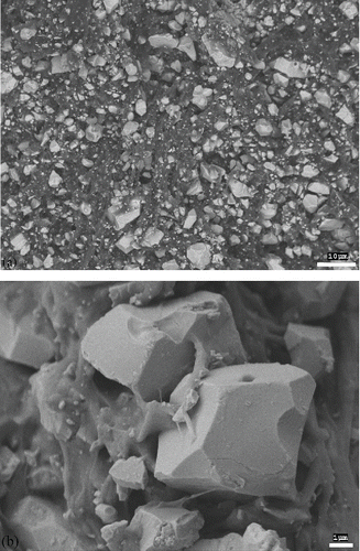
Figure 3. SEM micrographs PZT-ionomer composites (a) overview of the cross section and (b) the primary particles.

Figure 4. P-E hysteresis loops of (a) PZT-ionomer composites and (b) PZT ceramics at room temperature.
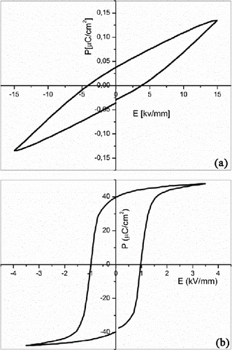
Figure 4. P-E hysteresis loops of (a) PZT-ionomer composites and (b) PZT ceramics at room temperature.

Table 1. Piezoelectric charge coefficients of the PZT-ionomer composites, obtained after poling under an electric field of 15 kV mm-1 with various temperatures and time [Citation6].

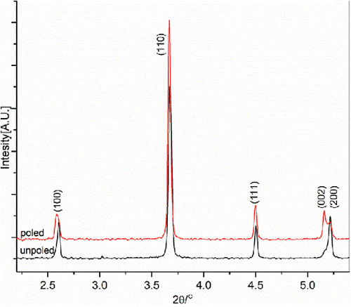
Figure 5. Integrated high energy synchrotron XRD patterns of PZT-ionomer composite, for ψ = 0°.

Figure 5. Integrated high energy synchrotron XRD patterns of PZT-ionomer composite, for ψ = 0°.

Figure 6. Schematic representation of strain development due to ferroelectric domain reorientation during the poling process [Citation16].

Figure 6. Schematic representation of strain development due to ferroelectric domain reorientation during the poling process [Citation16].

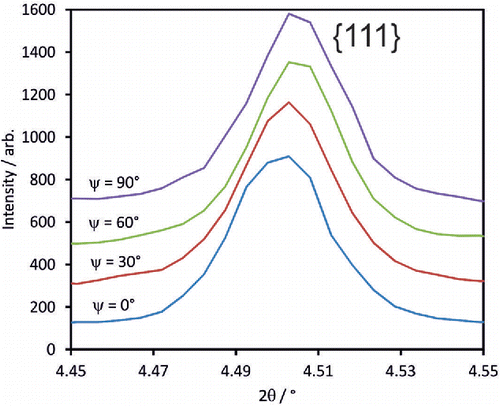
Figure 7. Changes in {111} peak position as a function of azimuthal angle Ψ for poled composite.

Figure 7. Changes in {111} peak position as a function of azimuthal angle Ψ for poled composite.

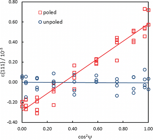
Figure 8. Lattice strain ϵ{111} –cos2 Ψ plots for unpoled and poled composites.

Figure 8. Lattice strain ϵ{111} –cos2 Ψ plots for unpoled and poled composites.

Figure 9. Changes in {200} peak profiles as a function of azimuthal angle, Ψ, for the poled composite.
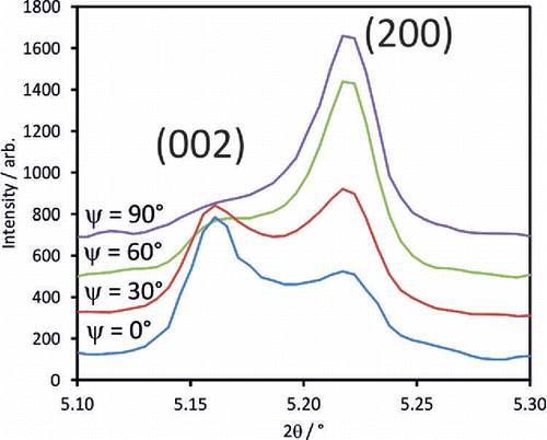
Figure 9. Changes in {200} peak profiles as a function of azimuthal angle, Ψ, for the poled composite.

Figure 10. Variation in fraction of c-axis oriented domains, ν(002), as a function of cos2 Ψ for unpoled and poled composites.
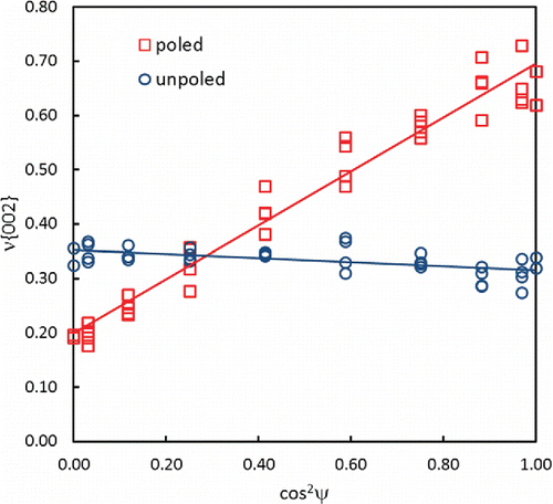
Figure 10. Variation in fraction of c-axis oriented domains, ν(002), as a function of cos2 Ψ for unpoled and poled composites.