
Figures & data
Figure 1. Major structural elements of western New Guinea and distribution of shallow earthquakes (<30 km depth). Tectonic features are shown (after Atmawinata et al. Citation1989; Hartono et al. Citation1989; Ratman et al. Citation1989; Pieters et al. Citation1989; Tobing et al. Citation1990; Baldwin et al. Citation2012; Hall Citation2012; Webb et al. Citation2019, Citation2020a, Citation2020b). Earthquake catalogue from GCMT (www.globalcmt.org) from 25 June 1976 to 1 July 2019. Figure base from the Digital Elevation Model (http://tides.big.go.id/DEMNAS/) and bathymetry from GEBCO (www.gebco.net). Pacific-Australian plate motion vector from DeMets et al. (Citation1994) and Stevens et al. (Citation2002). Dotted line (R.F.W.O.C.F. = Ransiki Fault-Weyland Overthrust connecting fault) is an inferred fault in western Cendrawasih Bay similar to the former suture shown by Dow and Sukamto (Citation1984) and Gold et al. (Citation2017b, figure 1). Inset shows the main plates in the New Guinea eastern Indonesia region.
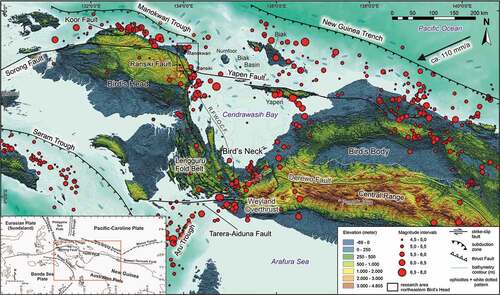
Figure 2. (a) Regional geological map of the Bird’s Head Peninsula simplified from Dow et al. (Citation1986), Watkinson and Hall (Citation2017), and Webb et al. (Citation2019). Bathymetry from GEBCO (www.gebco.net). Onland background of hillshade derived from the Digital Elevation Model (http://tides.big.go.id/DEMNAS/). (b) Simplified geological map of northeastern Bird’s Head Peninsula, Western New Guinea. Reinterpreted and updated from the 1:250 000 scale geological maps of Atmawinata et al. (Citation1989) and Ratman et al. (Citation1989). Triassic ages of intrusions from Webb et al. (Citation2019, Citation2020a, Citationb). Location shown on (a).
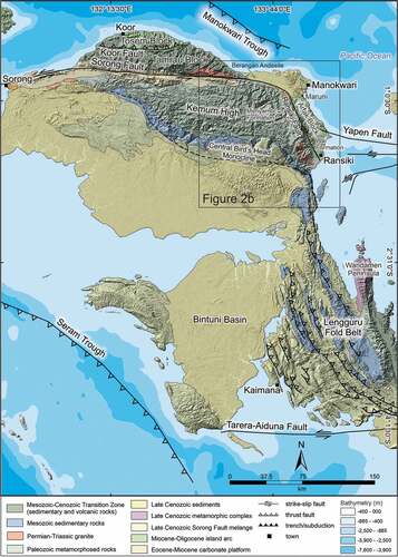
Figure 2. (Continued)
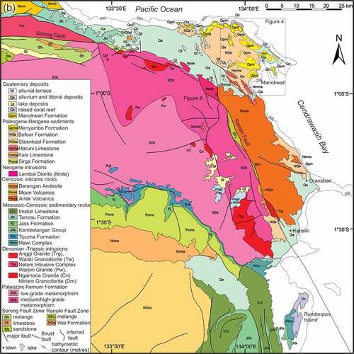
Figure 3. Topography of the Kemum High, Digital Elevation Model and topographic cross-section. Figure base made with GeoMapApp (www.geomapapp.org), CC by (Ryan et al. Citation2009).
Figure 4. Geological map of the Manokwari area showing northwest-southeast trending folds, with a substantial homoclinal dip to the southwest, and prominent anticlines cored by the Maruni Limestone in the southwest. Background of hillshade derived from the Digital Elevation Model (http://tides.big.go.id/DEMNAS/). Location shown on Reinterpreted and updated from the map of Ratman et al. (Citation1989) based on new mapping reported herein. Orientation data from the jungle-clad area west of the Nuni River (northwestern part of the area) is from Ratman et al. (Citation1989).
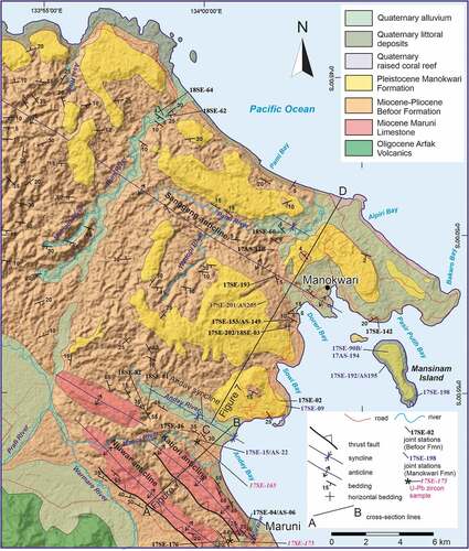
Figure 5. (a)-(d) Excavation in a quarry, Anday area, locality 17SE–165 (0°56’28.73“S, 133°59’51.00“E). Polymictic conglomerate in the Befoor Formation with clasts of granite (gr), diorite (dr), and limestone (lst). Hardened clay clasts are also present. The grain size is dominantly very coarse to fine grain/pebble, but some of the clasts have a granule size. (e) An excavation showing the contact between the Befoor Formation and the overlying Manokwari Formation, locality 17SE–39 (0°54’59.90“S, 134°1’31.70“E). Photograph shows contact (red dashed line) of reef limestone (Manokwari Formation) unconformably overlying grey mudstone (Befoor Formation). Close-up photograph given in (f).
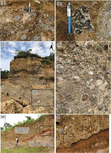
Figure 6. Lower hemisphere equal area stereonets for poles to bedding in the Befoor Formation and Maruni Limestone for the Manokwari area. (a) Domain 1 (north of the Anday syncline, cross-section CD). Fold axis (β) = 1°/120°. (b) Hingk area (southern part of the Kabori anticline) along road into limestone quarry. Fold axis (β) = 9°/326°. (c) All bedding in Domain 2 (Maruni area, cross-section AB). Fold axis (β) = 3°/317°. (d) Contoured plot of (c).
Figure 7. Cross-sections CD (a) and AB (b) of the Manokwari area. See Figure 4 for locations.
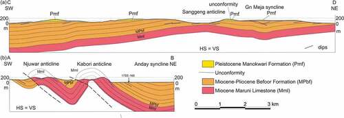
Figure 8. Road cutting in the Lembai Diorite; photographs taken looking to the west. (a) Shear zone (85°/065°) with left side (southwest) dropped relative to the northeastern side of the fault indicated by foliation curving into the fault plane, locality 18SE–167 (0°59’24.10“S, 133°53’4.80“E). (b) Calcite veins (dotted lines) in and adjacent to the shear zone. (c) Fault 75°/155° (in white square, see (d) for close-up photograph). (d) Slickenlines (fibrous calcite) in the fault in (c) with a pitch of 75° to the east. (e)-(f) Lower hemisphere equal-area stereonets of orientation data of structures measured in road cuttings in the Lembai Diorite (from north [0°59’19.6“S, 133°53’8.3“E] to south [0°59’39.6“S, 133°53’9.2“E]). (e) Poles to veins (126) contoured at 1, 2, 4, and 8% per 1% area. Average 79°/234°. (f) Faults and shear zones (9) plotted as great circles with slickenlines (7, black dots).
![Figure 8. Road cutting in the Lembai Diorite; photographs taken looking to the west. (a) Shear zone (85°/065°) with left side (southwest) dropped relative to the northeastern side of the fault indicated by foliation curving into the fault plane, locality 18SE–167 (0°59’24.10“S, 133°53’4.80“E). (b) Calcite veins (dotted lines) in and adjacent to the shear zone. (c) Fault 75°/155° (in white square, see (d) for close-up photograph). (d) Slickenlines (fibrous calcite) in the fault in (c) with a pitch of 75° to the east. (e)-(f) Lower hemisphere equal-area stereonets of orientation data of structures measured in road cuttings in the Lembai Diorite (from north [0°59’19.6“S, 133°53’8.3“E] to south [0°59’39.6“S, 133°53’9.2“E]). (e) Poles to veins (126) contoured at 1, 2, 4, and 8% per 1% area. Average 79°/234°. (f) Faults and shear zones (9) plotted as great circles with slickenlines (7, black dots).](/cms/asset/72b49c62-4099-4a7b-998f-19569d8fb174/tigr_a_2188404_f0008_c.jpg)
Figure 9. Plumose structure showing hackle fringe and propagation direction along a northeast-trending vertical joint in the Befoor Formation near Manokwari, locality 17SE–01 (0°52’30.08“S, 134° 2’49.16“E).
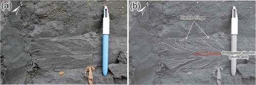
Figure 10. Lower hemisphere equal-area stereonets (number of poles to planes given at lower right for each stereonet) and photographs of joints in the Befoor Formation. (a) All joints/veins in the Manokwari area. (b) Contoured plot of (a) at 1, 2, 4 and 8% per 1% area. (c) Poles to joints (S0 25°/160°) at locality 18SE–60 with dominant east-southeast set of joints (0°46’4.21‘S, 133°58’37.50“E). Average orientation of the east-southeast joint set is 90°/206°. (d) Outcrop in the Pami River, same location as (c). (e) Outcrop in the Nuni River (locality 18SE–62, 0°46’12.8”S, 133°58’56.5’E). Average 76°/290°. (f) Road cutting in Befoor Formation showing 2 sets of joints/veins at locality 18SE–82 (0°55’36.968“S, 133°57’16.75“E). (g) Lower hemisphere equal-area stereonets of poles to veins from locality 18SE–82 (S0 not determined) with 2 average orientations (53°/301°, 61°/135°). (h) Locality 17SE–153/AS-149 (0°52’39.175“S, 134°2’45.688“E, S0 10°/220°) with several orientations of joints. (i) Poles to two joint sets at locality 17SE–202 (0°52’52.006“S, 134°2’41.992“E, S0 flat-lying), left average 77°/136°, right average 55°/226°.
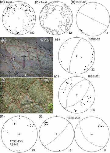
Figure 11. Lower hemisphere equal-area stereonets of structures in the Manokwari Formation. (a) Total poles to joints. (b) Total poles to joints contoured at 2, 4, and 6% per 1% area. (c) Poles of all joints measured at the three localities on Mansinam Island. (d) Outcrop of reef limestone of the Manokwari Formation at locality 17SE-09A (0°55’26.963“S, 134°2’39.792“E) showing joints and a fault plane. (e) Close-up photograph of the fault plane in (d) and showing down-dip slickenlines. (f) 19 poles to joints at locality 17SE-09A, with an average of 77°/005° for 12 joints. (g) Fault with slickenlines and principal stress directions. (h) Stylolitic joint on the western side of Mansinam Island (0°54’7.349“S, 134°5’44.443“E).
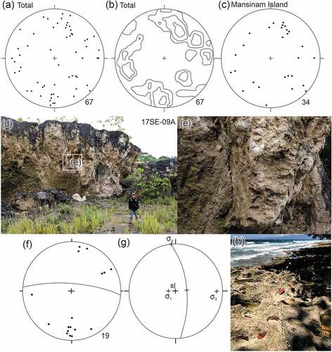
Figure 12. (A) Excavation in Befoor Formation that shows bedding (S0 20°/305°), small faults, and joints, locality 17SE–142 (0°52’39.751“S, 134°5’21.352“E). (b) Close-up of small fault showing gently plunging slickenlines. (c) Lower hemisphere equal-area stereonets; left, 3 great circles to faults, middle, 8 poles to joints, and right, principal stresses related to small sinistral strike-slip fault with slickenlines in (b). (d) Outcrop of fault scarp in the Befoor Formation overlain by Manokwari Formation at locality 17SE–40 (0°54’50.259“S, 134°1’30.528“E). (e) Steeply pitching slickenlines (dotted white line) along the fault surface (as shown in box in (d)). (f) Lower hemisphere equal-area stereonet showing normal fault (great circle), slickenlines (cross, sl) and principal stress orientations.
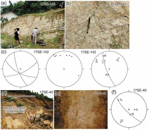
Figure 13. Detrital zircon ages from the Befoor Formation. (a-b) 238U/206Pb–207Pb/206Pb concordia diagrams (errors given at the 2σ level). (c-d) U–Pb age histogram and cumulative frequency plots.
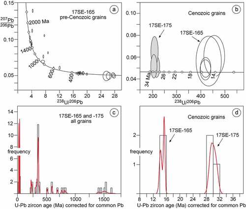
Figure 14. Time-space plot for the past 25 Ma showing comparisons of main stratigraphic units, main tectonic events and radiometric ages for the Manokwari area (Robinson and Ratman Citation1977; Gold et al. Citation2014, Citation2017a, Citation2017b; this work), the Tamrau and Tosem blocks (Pieters et al. Citation1989; Webb et al. Citation2019, Citation2020a, Citation2020b), the Central Bird’s Head Monocline (Pieters et al. Citation1985; Thery et al. Citation1999), Lengguru Fold Belt (Dow and Sukamto Citation1984; Bailly et al. Citation2009; White et al. Citation2019), Cendrawasih Bay (Babault et al. Citation2018), and the Central Ranges of western New Guinea (Cloos et al. Citation2005; Quarles van Otford and Cloos Citation2005). The 20 m thick drowning succession overlying the Maruni Limestone is described as an equivalent of the Segau Formation by Gold et al. (Citation2017b) from a locality 18 km south-southwest of Manokwari (see text). Radiometric ages for the Manokwari area from Pieters et al. (Citation1985, K-Ar age from the Lembai Diorite) and Webb et al. (Citation2020a, U-Pb zircon age from a diorite intrusion into the Arfak Volcanics, AVI). Radiometric ages for Tamrau Block from Webb et al. (Citation2020a, U-Pb zircon ages, Moon Volcanics). The Cendrawasih Bay column is based on seismic data and modelling after Babault et al. (Citation2018). Abbreviations: dzs, detrital zircon samples at approximate stratigraphic level in the Befoor Formation (this work, see text); SSS, sinistral strike-slip faulting in the Central Range.
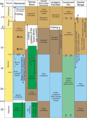
Figure 15. (a) Block diagram illustrating kinematic partitioning of oblique convergence (without scale) in northwestern New Guinea. GPS vector (black arrow) based on DeMets et al. (Citation1994), Bock et al. (Citation2003) and Puntodewo et al. (Citation1994). The diagram shows partitioning as is occurring in the last 4 Ma and also notes the timing of major shortening events in the region (Cloos et al. Citation2005; White et al. Citation2019; this paper). Note that shortening in the Lengguru Fold Belt region (including the adjacent Wandamen Peninsula) was replaced by extension post 3 Ma. (b) Block diagram showing oblique convergence (adapted from McCaffrey Citation2009).
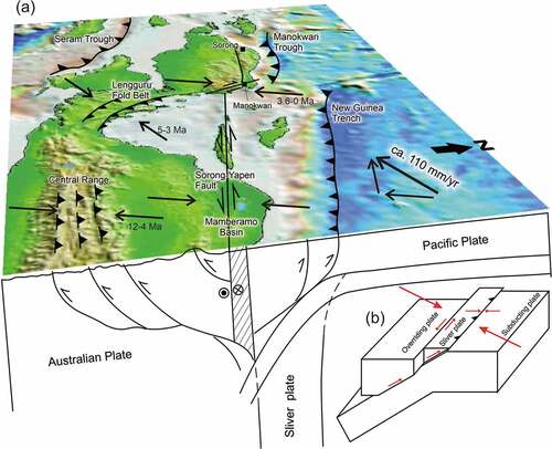
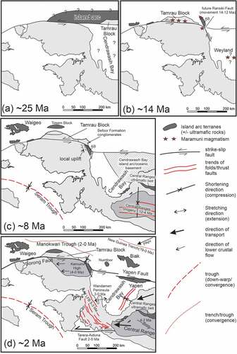
Figure 16. Tectonic evolution of the Bird’s Head Peninsula in the last 25 Ma influenced by oblique convergence of the Australian, Philippine Sea and Pacific-Caroline plates (see text). Oblique plate convergence is resolved into north-northeast shortening and sinistral east-west strike-slip faulting. (a) Docking of an island arc terrane of unknown extent at ~ 25 Ma accompanied by development of the Sorong Fault. (b) At ~ 14 Ma strike-slip movement has ceased along the Sorong Fault after offset of the Tamrau Block (Webb et al. Citation2019, Citation2020a) and followed by oblique subduction (trench not shown) to form the Maramuni igneous rocks. This preceded dextral movement along the Ransiki Fault that offset the Arfak Block (AB) southwards. Location of the Maramuni igneous rocks in the Weyland Overthrust is uncertain but must have lain north of their present location. (c) At ~ 8 Ma major orogeny was active in the Central Range (Sapiie and Cloos Citation2004; Cloos et al. Citation2005). It is uncertain when subduction was initiated along the New Guinea Trench. No major strike-slip movement occurred since 12 Ma along the Sorong Fault as shown by the tie point indicated by uplift of the northeastern Kemum Block and adjacent Arfak Block (AB) that provided a source of detritus to the Befoor Formation. Strike-slip movements may have been more substantial along faults (not shown) in the island arc terrane north of New Guinea. Basement to Cendrawasih Bay was transported from the northeast during the interval 8–6 Ma to its approximate present location (Francois et al. Citation2016; Babault et al. Citation2018). Shortening in the Central Range accompanied by southward emplacement of the Central Range ultramafic belt initiated at 12 Ma (Cloos et al. Citation2005). The Tosem Block was being emplaced southwards onto the northern part of the Bird’s Head Peninsula (Webb et al. Citation2020a). (d) At ~ 2 Ma shortening had been completed in the Lengguru Fold Belt and Wandamen Peninsula (5–3 Ma, White et al. Citation2019). North-northeast convergence is accommodated by subduction along the New Guinea Trench and the Manokwari Trough (past ~ 2–1 Ma only). Limited sinistral strike-slip faulting along the Yapen Fault and in the Central Range (at 4–2 Ma, Sapiie and Cloos Citation2004; Sapiie Citation2016). North-northeast shortening caused folding in the Manokwari area, shortening, and resulting uplift of the Kemum High (also accommodates limited strike-slip movement along the Sorong Fault). Extension occurred from <3 Ma in the Wandamen Peninsula (White et al. Citation2019).
Supplemental Material
Download Zip (578.2 KB)Data availability statement
The supplemental data that support the findings of this study are openly available in Figshare at http://doi.org/10.6084/m9.figshare.21514389.