
Figures & data
Table 1. Resent publications on sustainable reconfigurable manufacturing.
Figure 1. Design for responsive and sustainable reconfigurable RMS.
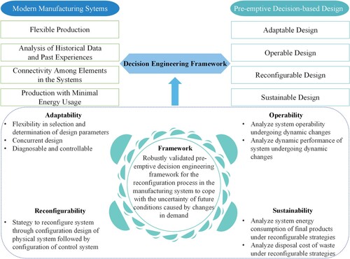
Figure 2. Problem description – Design and analyse of responsive and sustainable RMS.
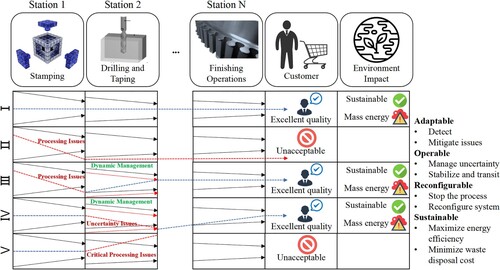
Figure 3. Proposed method – Implication for DEF development.
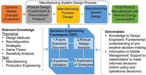
Figure 4. The proposed specific process to explore the decision network for sustainable RMS reconfiguration strategy.
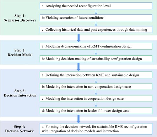
Figure 5. The six axes of degree of freedom.
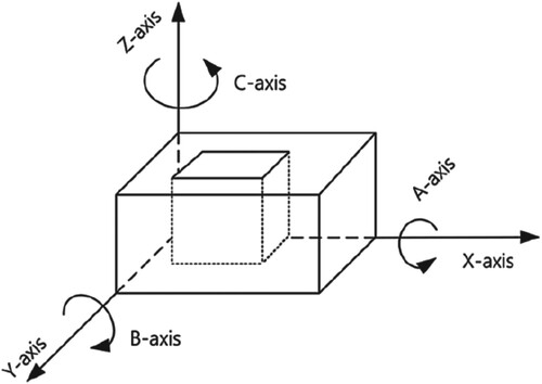
Figure 6. Solution space exploration in weak-weak interaction (a), strong-strong interaction (b), and strong-weak interaction (c).
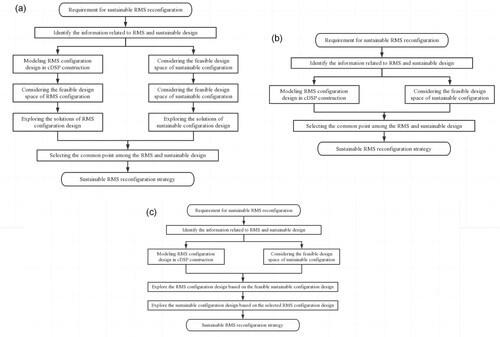
Figure 7. Decision network for exploring the sustainable RMS reconfiguration strategy.
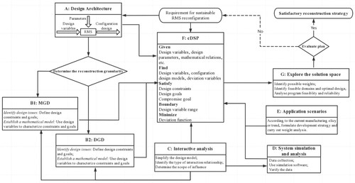
Table 2. RMT basic modules and the corresponding energy consumption (Sullivan, Burnham, and Wang Citation2010).
Figure 8. The example of the L4 (right) and V8 (left) engine block (a) and three types of the cylinder block (b) (Abbas and ElMaraghy Citation2016).
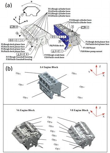
Table 3. Key operation for L4, V6 and V8 engine cylinder production (Milisavljevic-Syed et al. Citation2020a).
Figure 9. The RMS initial configuration in text example.
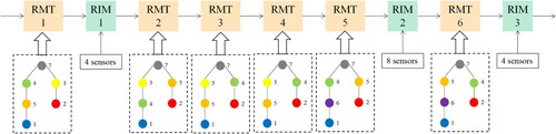
Figure 10. The solution of Phase A with (a) and without (b) considering energy consumption.
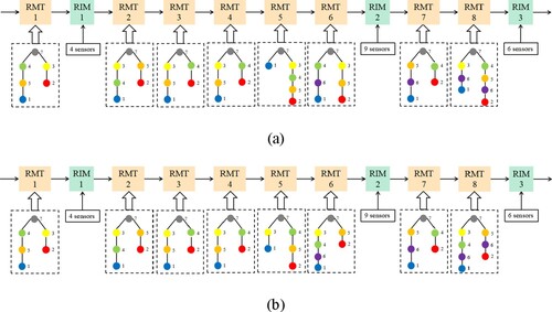
Figure 11. The solution of Phase B with (a) without (b) considering energy consumption.
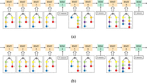
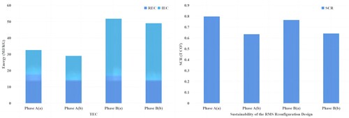
Figure 12. Results of sustainability for each phase with and without considering energy consumption.
Data availability statement
The data that support the findings of this study are available from the corresponding author, Milisavljevic-Syed, J., upon reasonable request.