Figures & data
Figure 1. Schematic illustrations of sub-response matrices. (a) Transmission probability. (b) Neighbor-induced production probability. (c) Self-induced production probability. (d) Escape probability.
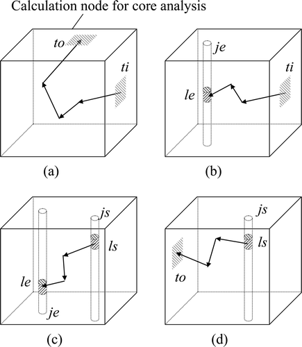
Figure 2. Schematic illustration of sub-surfaces and angular segments.
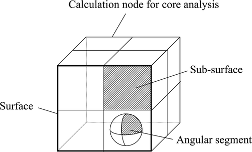
Table 1. Core characteristics and fuel assembly specifications of BASALA experiments.
Figure 3. Configuration of reference core for core 1. The percentages are wt % of Pu total content and the numbers are the numbers of each type of rod.
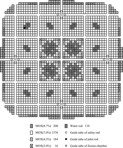
Figure 4. Configuration of reference core for core 2. The percentages are wt % of Pu total content and the numbers are the numbers of each type of rod.
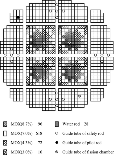
Figure 5. Configuration of 8Gd core for core 1. The percentages are wt % of Pu total content and the numbers are the numbers of each type of rod.
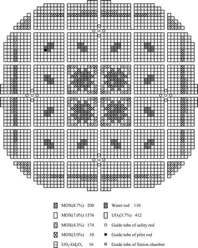
Figure 6. Configuration of 16Gd core for core 1. The percentages are wt % of Pu total content and the numbers are the numbers of each type of rod.
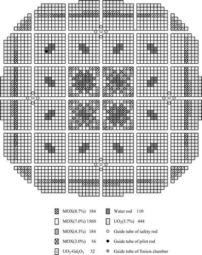
Figure 7. Configuration of 8Gd core for core 2. The percentages are wt % of Pu total content and the numbers are the numbers of each type of rod.
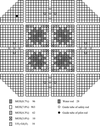
Figure 8. Configuration of 16Gd core for core 2. The percentages are wt % of Pu total content and the numbers are the numbers of each type of rod.
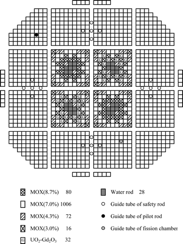
Figure 9. Configuration of 2D void core for core 1. The percentages are wt % of Pu total content and the numbers are the numbers of each type of rod.
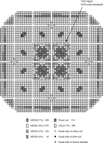
Figure 10. Configuration of water rod core for core 1. The percentages are wt % of Pu total content and the numbers are the numbers of each type of rod.
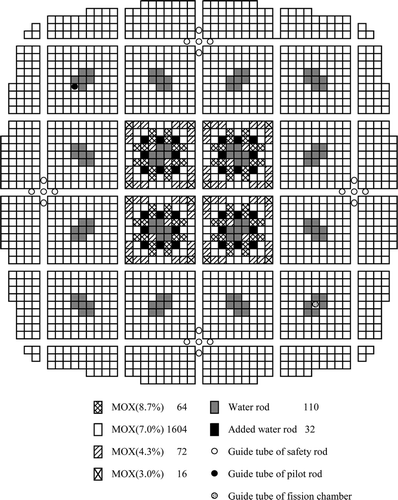
Figure 11. Configuration of control blade inserted core for core 2. The percentages are wt % of Pu total content and the numbers are the numbers of each type of rod.
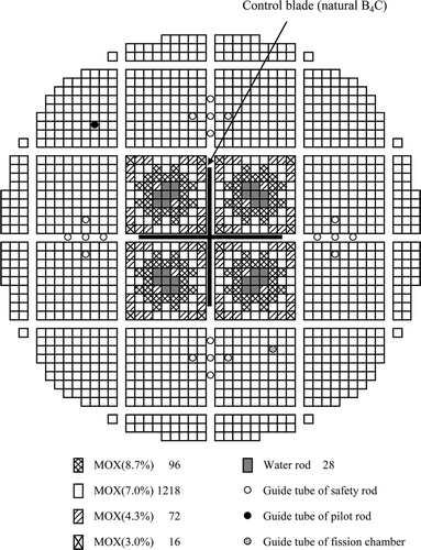
Figure 12. Illustrations of sub-surfaces and angular segments. (a) Number of sub-surfaces and angular segments : 4 × 4 and 4. (b) Number of sub-surfaces and angular segments : 4 × 4 and 16.
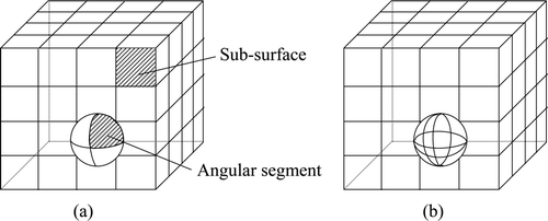
Table 2. Energy group structure for sub-response matrices.
Table 3. Critical k-effective values for reference cores.
Figure 13. Fuel rod fission rate distribution of reference core for core 1 (diagonal direction).
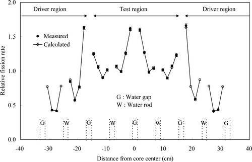
Figure 14. Fuel rod fission rate distribution of reference core for core 2 (diagonal direction).
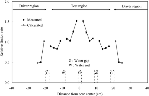
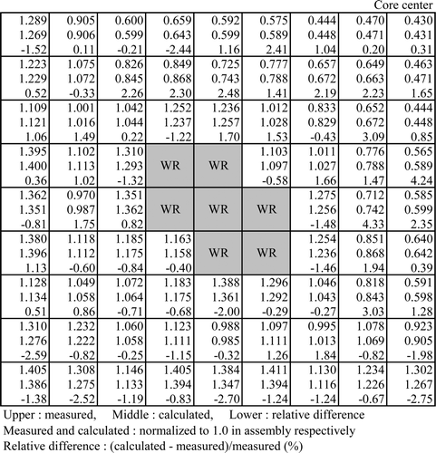
Table 4. Root mean square and maximum differences of fuel rod fission rate distribution between calculation and measurement in diagonal direction for reference cores (unit:%).
Figure 15. Fuel rod fission rate distribution of reference core for core 1 (test assembly).
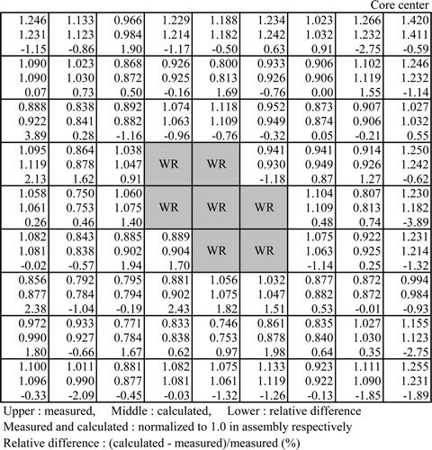
Table 5. Root mean square and maximum differences of fuel rod fission rate distribution between calculation and measurement in test assembly for reference cores (unit:%).
Figure 16. Fuel rod fission rate distribution of reference core for core 2 (test assembly).
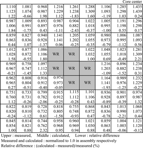
Table 6. Critical k-effective values.
Figure 17. Fuel rod fission rate distribution of 8Gd core for core 1 (diagonal direction).
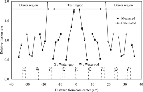
Table 7. Root mean square and maximum differences of fuel rod fission rate distribution between calculation and measurement in diagonal direction (unit:%).
Figure 18. Fuel rod fission rate distribution of 16Gd core for core 1 (diagonal direction).
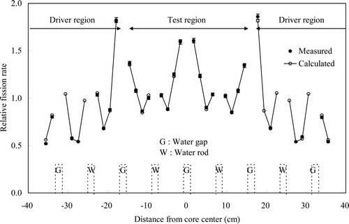
Figure 19. Fuel rod fission rate distribution of 8Gd core for core 2 (diagonal direction).
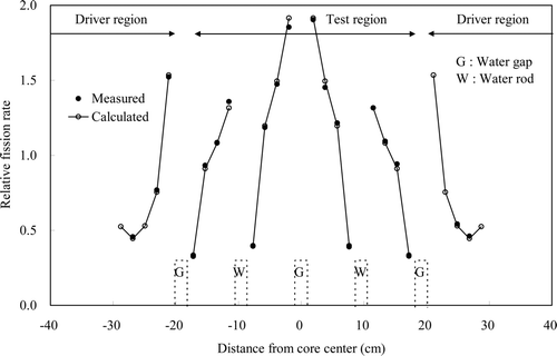
Figure 20. Fuel rod fission rate distribution of 16Gd core for core 2 (diagonal direction).
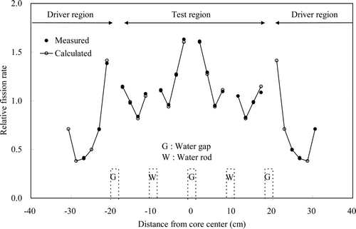
Figure 21. Fuel rod fission rate distribution of 2D void core for core 1 (diagonal direction).
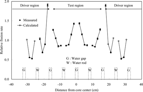
Figure 22. Fuel rod fission rate distribution of water rod core for core 1 (diagonal direction).
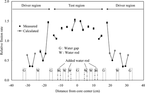
Figure 23. Fuel rod fission rate distribution of control blade inserted core for core 2 (diagonal direction).
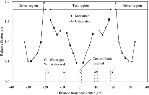
Figure 24. Fuel rod fission rate distribution of 8Gd core for core 1 (test assembly).

Table 8. Root mean square and maximum differences of fuel rod fission rate distribution between calculation and measurement in test assembly (unit: %).
Figure 25. Fuel rod fission rate distribution of 16Gd core for core 1 (test assembly).
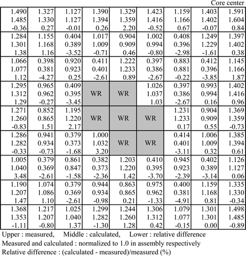
Figure 26. Fuel rod fission rate distribution of 8Gd core for core 2 (test assembly).
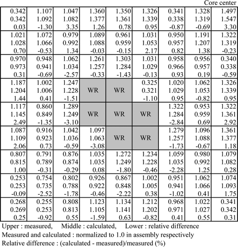
Figure 27. Fuel rod fission rate distribution of 16Gd core for core 2 (test assembly).
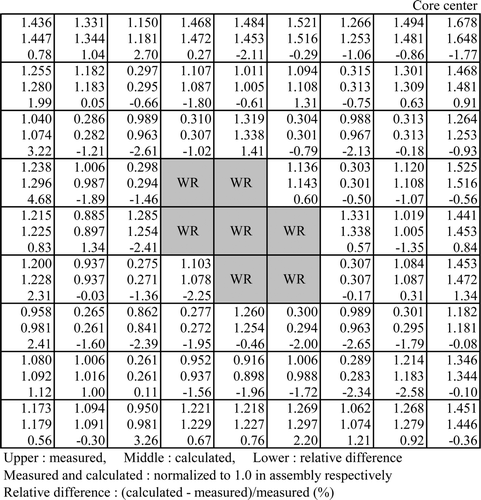
Figure 28. Fuel rod fission rate distribution of 2D void core for core 1 (test assembly).
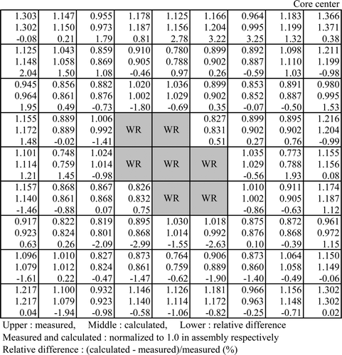
Figure 29. Fuel rod fission rate distribution of water rod core for core 1 (test assembly).
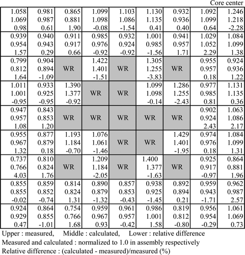
Figure 30. Fuel rod fission rate distribution of control blade inserted core for core 2 (test assembly)