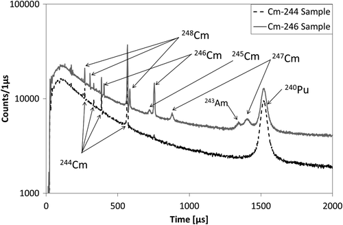
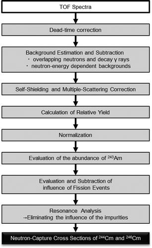
Figures & data
Figure 1. A side view of NNRI. The neutron beam emitted from the moderator goes through the T0 chopper, neutron filter, disk choppers, collimators and the two detector systems, and then is dumped into the beam stopper. The sample positions for the array of large Ge detectors and NaI detectors are 21.5 and 27.9 m from the moderator, respectively.
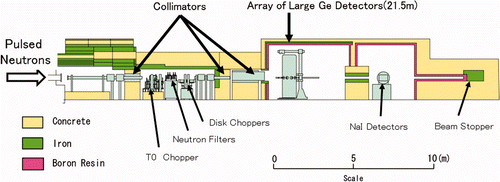
Figure 2. Layout of the array of Ge detectors. The array is composed of two cluster-Ge detectors, eight coaxial-Ge detectors and anti-coincidence shields around each Ge detector.
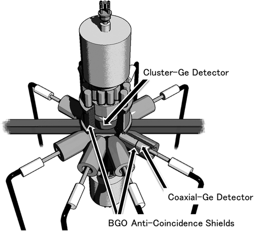
Table 1. Isotopic and chemical impurities of curium oxide in the 244Cm and 246Cm samples [15].
Figure 3. γ-ray pulse-height spectra from the 244Cm sample with neutron beam (red solid line), the dummy case (black dotted line), and a decay γ-ray pulse-height spectrum from the 244Cm sample without neutron beam (blue dashed line) measured with one of the crystals.
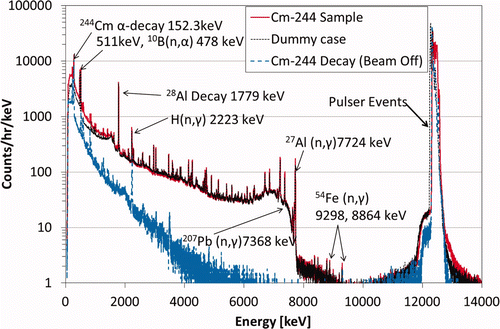
Figure 4. γ-ray pulse-height spectra from the 246Cm sample with neutron beam (red solid line), the dummy case (black dotted line), and a decay γ-ray pulse-height spectrum from the 246Cm sample without neutron beam (blue dashed line) measured with one of the crystals.
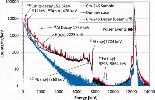
Figure 5. The resonance-gated net spectrum (black solid line) and the sum of the resonance-gated γ-ray pulse-height spectra (gray solid line) in the first resonance of 240Pu in the 246Cm sample data.
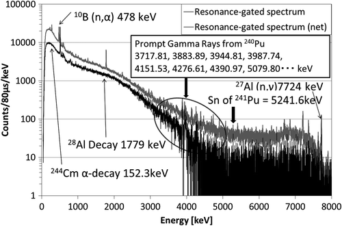
Figure 6. The resonance-gated net spectra in the first resonance of 244Cm from the 244Cm sample (black dashed line) and the 246Cm sample (gray solid line). Asterisks (*) indicate previously unknown γ-rays.
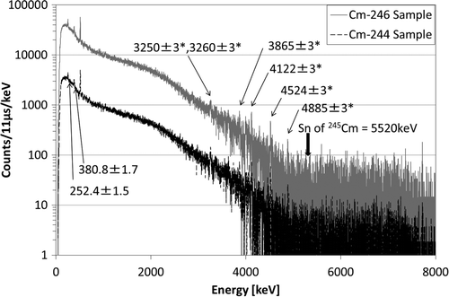
Table 2. Observed γ-ray energies and transition assignments.
Figure 7. The resonance-gated net spectrum in the first resonance of 246Cm from the 246Cm sample. Asterisks (*) indicate previously unknown γ-rays.
Figure 10. A typical time dependence of the live-to-real time ratio (red dotted line) and the corresponding TOF spectra with (blue dashed line) and without (black solid line) the dead-time correction from the 246Cm sample measured with one of the Ge crystals.
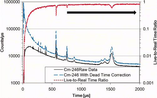
Figure 11. A typical TOF spectrum measured with one of the crystals (blue dotted line), the corresponding TOF dependence of the area count due to the random timing pulses (red dashed line), the TOF spectra with the dead-time correction (light-blue solid line), the fitted curve (black dashed-dotted line), and the deduced background (black solid line) in the 0–80 ms TOF range from the 246Cm sample.
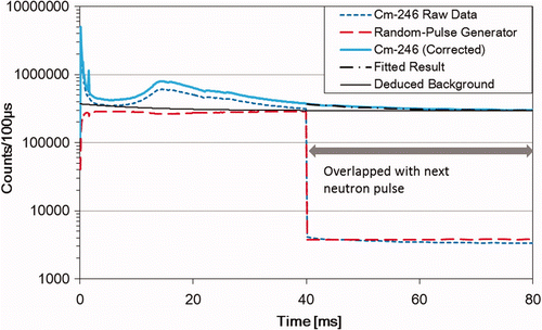
Figure 12. A typical estimated background of the 246Cm sample measured with one of the crystals (red dashed line) and the corresponding TOF spectrum minus the background due to overlapping neutrons and decay γ-rays (black solid line).
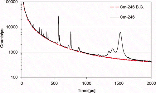
Figure 13. The sum TOF spectra of the 244Cm sample (black solid line) and the 246Cm sample (gray solid line) and the uncertainties of the 244Cm sample (black dashed line) and the 246Cm sample (gray dashed line).
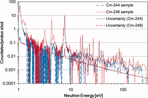
Figure 14. Correction factors for neutron self-shielding and multiple scattering for the 246Cm sample (gray solid line) and the 244Cm sample (black dashed line).
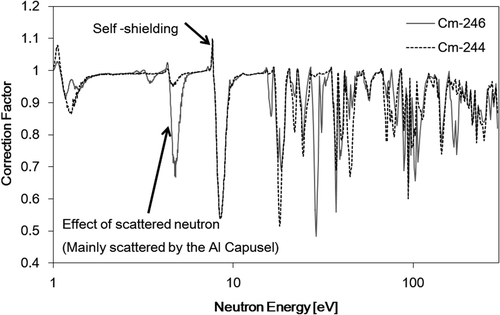
Figure 15. The averaged neutron flux at the 21.5-m sample position (black solid line) and neutron-energy-dependent errors (gray dashed line).
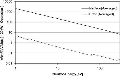
Figure 16. The normalized yields weighted by the abundance listed in Table 1 (red solid line); the contributions from neutron-capture events of 240Pu, 243Am, and 244, 246Cm (black dashed line); and uncertainties in the contributions (blue dotted line) from the 244Cm sample in the neutron energy region from 1 to 100 eV.
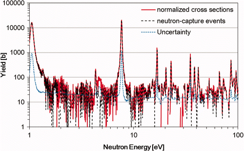
Figure 17. The normalized yields weighted by the abundance listed in Table 1 (red solid line); the contributions from neutron-capture events of 240Pu, 243Am, and 244, 246, 248Cm (black dashed line); and uncertainties in the contributions (blue dotted line) from the 246Cm sample in the neutron energy region from 1 to 100 eV.
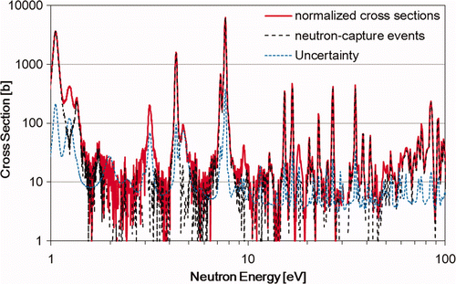
Table 3. Obtained resonance parameters along with the evaluations of JENDL-4.0 [16].
Figure 18. The obtained capture yields weighted by the abundance in Table 1 (gray circles), with the corresponding uncertainties (black dashed line), the SAMMY [26]-fitted results for all nuclides (purple solid line), 244Cm (red dashed line), 246Cm (blue dashed line), 243Am (orange dashed line), and 240Pu (green dashed line) using the parameters shown in Table 4 (below 30 eV) and the JENDL-4.0 [16] (above 30 eV) in the neutron energy region from 1 to 100 eV for the 244Cm sample.
![Figure 18. The obtained capture yields weighted by the abundance in Table 1 (gray circles), with the corresponding uncertainties (black dashed line), the SAMMY [26]-fitted results for all nuclides (purple solid line), 244Cm (red dashed line), 246Cm (blue dashed line), 243Am (orange dashed line), and 240Pu (green dashed line) using the parameters shown in Table 4 (below 30 eV) and the JENDL-4.0 [16] (above 30 eV) in the neutron energy region from 1 to 100 eV for the 244Cm sample.](/cms/asset/fbcd7108-004a-4903-9900-0ade63ad357b/tnst_a_693887_o_f0018g.jpg)
Figure 19. The obtained capture yields weighted by the abundance in Table 1 (gray circles), with the corresponding uncertainties (black dashed line), the SAMMY [26]-fittedresults for all nuclides (purple solid line), 246Cm (red dashed line), 244Cm (blue dashed line), 248Cm (light green dashed line), 243Am (orange dashed line), and 240Pu (green dashed line) using the parameters shown in (below 30 eV) and the JENDL-4.0 [16] (above 30 eV) in the neutron energy region from 1 to 100 eV for the 246Cm sample.
![Figure 19. The obtained capture yields weighted by the abundance in Table 1 (gray circles), with the corresponding uncertainties (black dashed line), the SAMMY [26]-fittedresults for all nuclides (purple solid line), 246Cm (red dashed line), 244Cm (blue dashed line), 248Cm (light green dashed line), 243Am (orange dashed line), and 240Pu (green dashed line) using the parameters shown in Table 4 (below 30 eV) and the JENDL-4.0 [16] (above 30 eV) in the neutron energy region from 1 to 100 eV for the 246Cm sample.](/cms/asset/d297e2a9-9565-4e2d-bf2e-0197474b4028/tnst_a_693887_o_f0019g.jpg)
Figure 21. The capture yields weighted by the abundance in Table 1 from the 246Cm sample with error bars (blue circles), the SAMMY [26] fits using the parameters shown in Table 4 (blue solid line), and comparison to JENDL-4.0 [16] (broadened with SAMMY, black dashed line) around the first resonance of 246Cm.
![Figure 21. The capture yields weighted by the abundance in Table 1 from the 246Cm sample with error bars (blue circles), the SAMMY [26] fits using the parameters shown in Table 4 (blue solid line), and comparison to JENDL-4.0 [16] (broadened with SAMMY, black dashed line) around the first resonance of 246Cm.](/cms/asset/4990a2e0-e572-43f1-8521-5b8c06cb5948/tnst_a_693887_o_f0021g.jpg)
Figure 20. The capture yields weighted by the abundance in Table 1 from the 244Cm sample (red circles) and the 246Cm sample (blue triangles) with error bars, the results of the SAMMY [26] fits using the parameters shown in Table 4 (244Cm sample: red solid line, 246Cm sample: blue solid line), and comparison to JENDL-4.0 [16] (broadened with SAMMY, 244Cm sample: black dotted line, 246Cm sample: black dashed line) around the first resonance of 244Cm.
![Figure 20. The capture yields weighted by the abundance in Table 1 from the 244Cm sample (red circles) and the 246Cm sample (blue triangles) with error bars, the results of the SAMMY [26] fits using the parameters shown in Table 4 (244Cm sample: red solid line, 246Cm sample: blue solid line), and comparison to JENDL-4.0 [16] (broadened with SAMMY, 244Cm sample: black dotted line, 246Cm sample: black dashed line) around the first resonance of 244Cm.](/cms/asset/40037ac1-f6ac-4c52-a7c3-fa6af721c2d5/tnst_a_693887_o_f0020g.jpg)
Figure 22. Deduced neutron-capture cross-sections of 244Cm (black circles with gray error bars) and comparison to those measured by Moore [4] (blue triangles with blue err bars) and broadened JENDL-4.0 [16].
![Figure 22. Deduced neutron-capture cross-sections of 244Cm (black circles with gray error bars) and comparison to those measured by Moore [4] (blue triangles with blue err bars) and broadened JENDL-4.0 [16].](/cms/asset/c38a2d27-92a2-4a30-b647-d3a94ef823ae/tnst_a_693887_o_f0022g.jpg)
Figure 23. Deduced neutron-capture cross-sections of 246Cm (black circles with gray error bars) and comparison to those measured by Moore [4] (blue triangles with blue err bars) and broadened JENDL-4.0 [16].
![Figure 23. Deduced neutron-capture cross-sections of 246Cm (black circles with gray error bars) and comparison to those measured by Moore [4] (blue triangles with blue err bars) and broadened JENDL-4.0 [16].](/cms/asset/15524b07-ac40-44b9-a5bd-7a320e3a4818/tnst_a_693887_o_f0023g.jpg)
Figure 24. The ratios of sensitivities of the first and second resonances of 246Cm and the first, second, third, and forth resonances of 244Cm to that of 240Pu at the first resonance were calculated.
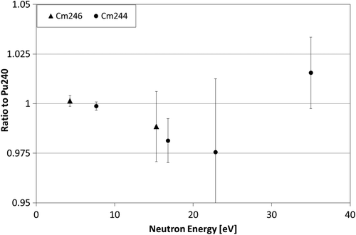
Figure 25. The deduced neutron-capture cross-sections of 244Cm (black circles; contribution from error sources to the uncertainties of the cross-sections, total error: red solid line; the abundances of 240Pu: black solid line; the evaluated value of JENDL-4.0 [16] of the first resonance of 240Pu: black dashed line; the contribution of fission events: blue dashed line; statistic: green solid line; self-shielding and multiple scattering: green dashed line; and systematic one in the normalization: purple solid line) around the first resonance of 244Cm.
![Figure 25. The deduced neutron-capture cross-sections of 244Cm (black circles; contribution from error sources to the uncertainties of the cross-sections, total error: red solid line; the abundances of 240Pu: black solid line; the evaluated value of JENDL-4.0 [16] of the first resonance of 240Pu: black dashed line; the contribution of fission events: blue dashed line; statistic: green solid line; self-shielding and multiple scattering: green dashed line; and systematic one in the normalization: purple solid line) around the first resonance of 244Cm.](/cms/asset/0ddb0d99-e384-4b11-80d1-b26f2e82d459/tnst_a_693887_o_f0025g.jpg)
Figure 26. The deduced neutron-capture cross-sections of 246Cm (black circles; contribution from error sources to the uncertainties of the cross-sections, total error: red solid line; the abundances of 240Pu: black solid line; the evaluated value of JENDL-4.0 [16] of the first resonance of 240Pu: black dashed line; isotopic ratio of 244Cm to 246Cm: blue solid line; the contribution of fission events: blue dashed line; statistic: green solid line; self-shielding and multiple scattering: green dashed line; and systematic one in the normalization: purple solid line) around the first resonance of 246Cm.
![Figure 26. The deduced neutron-capture cross-sections of 246Cm (black circles; contribution from error sources to the uncertainties of the cross-sections, total error: red solid line; the abundances of 240Pu: black solid line; the evaluated value of JENDL-4.0 [16] of the first resonance of 240Pu: black dashed line; isotopic ratio of 244Cm to 246Cm: blue solid line; the contribution of fission events: blue dashed line; statistic: green solid line; self-shielding and multiple scattering: green dashed line; and systematic one in the normalization: purple solid line) around the first resonance of 246Cm.](/cms/asset/de1a422d-fafc-4600-8141-94c8416bd824/tnst_a_693887_o_f0026g.jpg)
