867
Views
3
CrossRef citations to date
0
Altmetric
Technical Material

An experimental result on flaw sizing of steam generator tube at nuclear power plants using ultrasonic testing

, &
Pages 760-767 | Received 07 Feb 2012, Accepted 03 Apr 2012, Published online: 22 Jun 2012

Figures & data

Figure 1. Ultrasonic beam orientations to detect axial and circumferential oriented flaws. (a) Transducer configuration for wall loss and axial crack. (b) Transducer configuration for circumferential crack.
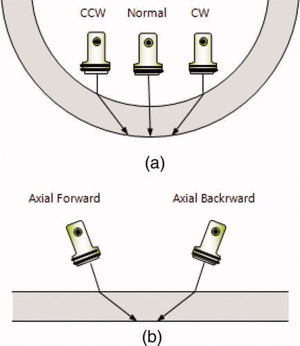
Figure 1. Ultrasonic beam orientations to detect axial and circumferential oriented flaws. (a) Transducer configuration for wall loss and axial crack. (b) Transducer configuration for circumferential crack.

Figure 2. The modeling result of normal beam sound field focused at middle of tube thickness. (a) C-scan image. (b) B-scan image.
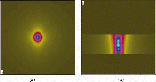
Figure 2. The modeling result of normal beam sound field focused at middle of tube thickness. (a) C-scan image. (b) B-scan image.

Figure 3. The modeling result of CCW and CW beam sound field focused at middle of tube thickness. (a) C-scan image. (b) B-scan image.
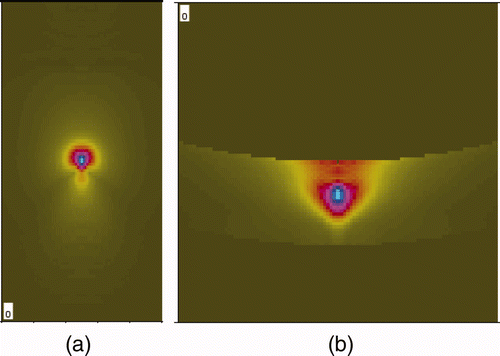
Figure 3. The modeling result of CCW and CW beam sound field focused at middle of tube thickness. (a) C-scan image. (b) B-scan image.

Figure 4. The modeling result of backward and forward beam sound field focused at middle of thickness. (a) C-scan image. (b) B-scan image.
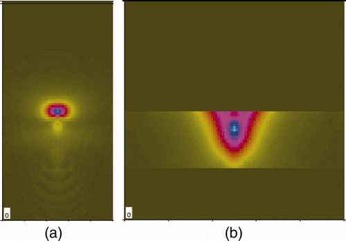
Figure 4. The modeling result of backward and forward beam sound field focused at middle of thickness. (a) C-scan image. (b) B-scan image.

Figure 5. Ultrasonic transducer for steam generator tube inspection designed based on the modeling result. (a) Modeling result. (b) Manufactured multi-array ultrasonic assembly.
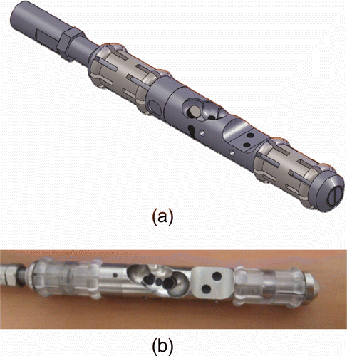
Figure 5. Ultrasonic transducer for steam generator tube inspection designed based on the modeling result. (a) Modeling result. (b) Manufactured multi-array ultrasonic assembly.

Table 1. Ultrasonic characteristic measurement of each element (at 6 dB).

Table 2. Dimensional specification of steam generator tube specimen.

Figure 6. Test tube drawing for the steam generator ultrasonic testing experiment with artificial flaws (unit : mm).
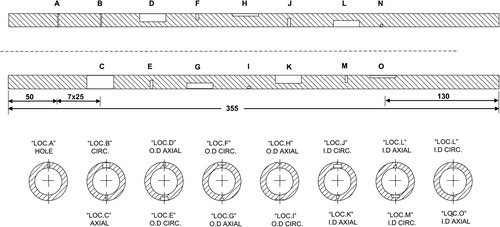
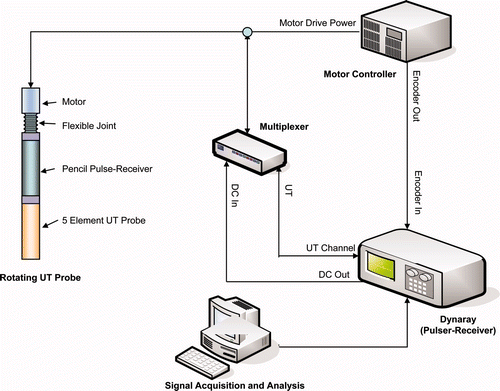
Figure 6. Test tube drawing for the steam generator ultrasonic testing experiment with artificial flaws (unit : mm).
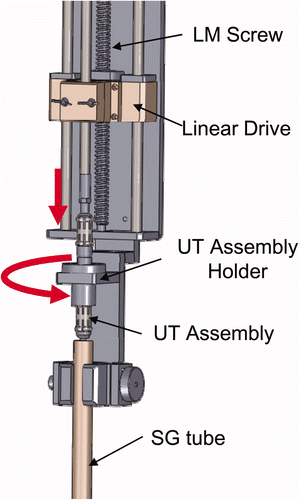
Table 3. Detail dimensions of EDM flaws embedded in steam generator tube.

Figure 7. The schematic diagram of ultrasonic experiment system.

Figure 7. The schematic diagram of ultrasonic experiment system.

Figure 8. Experimental apparatus for linear driving of rotating ultrasonic probe.

Figure 8. Experimental apparatus for linear driving of rotating ultrasonic probe.

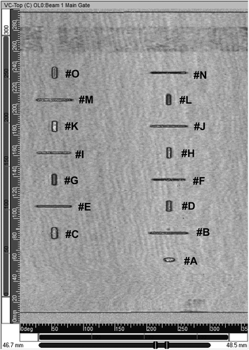
Figure 9. The experimental result showing C-Scan image from 0° degree transducer signal.

Figure 9. The experimental result showing C-Scan image from 0° degree transducer signal.

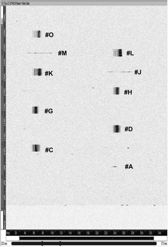
Figure 10. C-Scan signals of flaws detected by using CW transducer.

Figure 10. C-Scan signals of flaws detected by using CW transducer.

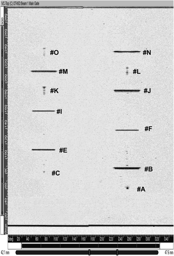
Figure 11. C-Scan signals of flaws detected by using backward transducer.

Figure 11. C-Scan signals of flaws detected by using backward transducer.

Table 4. Sizing results of detected flaws.

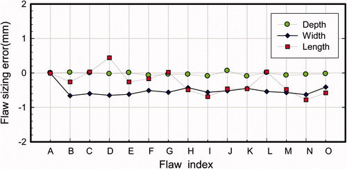
Figure 12. Comparison of measured flaw size errors based on flaw length, width and depth for each flaws.

Figure 12. Comparison of measured flaw size errors based on flaw length, width and depth for each flaws.

Reprints and Corporate Permissions

Please note: Selecting permissions does not provide access to the full text of the article, please see our help page How do I view content?

To request a reprint or corporate permissions for this article, please click on the relevant link below:

Academic Permissions

Please note: Selecting permissions does not provide access to the full text of the article, please see our help page How do I view content?

Obtain permissions instantly via Rightslink by clicking on the button below:

If you are unable to obtain permissions via Rightslink, please complete and submit this Permissions form. For more information, please visit our Permissions help page.