742
Views
6
CrossRef citations to date
0
Altmetric
Articles

An optimization approach to establish an appropriate energy group structure for BWR pin-by-pin core analysis

, , , , , & show all
Pages 689-707 | Received 30 Sep 2011, Accepted 13 Apr 2012, Published online: 22 Jun 2012

Figures & data

Figure 1. Geometry of 2 × 2 multi-assembly.

Figure 1. Geometry of 2 × 2 multi-assembly.

Figure 2. Variation of neutron spectrum due to spectral interference effect.

Figure 2. Variation of neutron spectrum due to spectral interference effect.

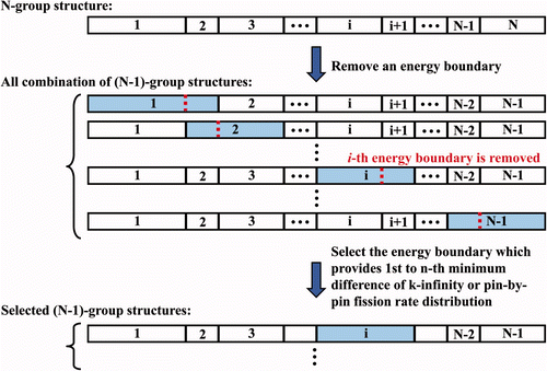
Figure 3. Concept of successive collapsing method.

Figure 3. Concept of successive collapsing method.

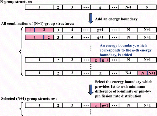
Figure 4. Concept of successive expanding method.

Figure 4. Concept of successive expanding method.

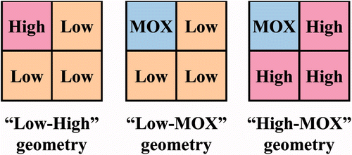
Figure 5. Geometries of three types of 2 × 2 multi-assembly.

Figure 5. Geometries of three types of 2 × 2 multi-assembly.

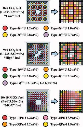
Figure 6. Geometries of three types of typical BWR fuel assemblies.

Figure 6. Geometries of three types of typical BWR fuel assemblies.

Figure 7. Difference of k-infinity and pin-by-pin fission rate distribution in Low-High geometry using the energy group structures obtained by various calculation methods.
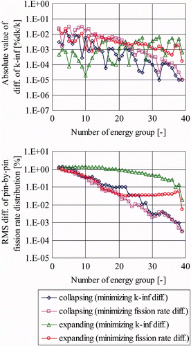
Figure 7. Difference of k-infinity and pin-by-pin fission rate distribution in Low-High geometry using the energy group structures obtained by various calculation methods.

Figure 8. Difference of k-infinity and pin-by-pin fission rate distribution in Low-MOX geometry using the energy group structures obtained by various calculation methods.
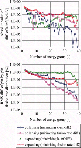
Figure 8. Difference of k-infinity and pin-by-pin fission rate distribution in Low-MOX geometry using the energy group structures obtained by various calculation methods.

Figure 9. Difference of k-infinity and pin-by-pin fission rate distribution in High-MOX geometry using the energy group structures obtained by various calculation methods.
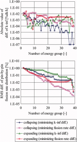
Figure 9. Difference of k-infinity and pin-by-pin fission rate distribution in High-MOX geometry using the energy group structures obtained by various calculation methods.

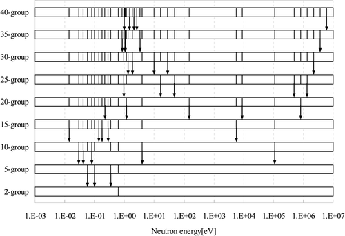
Figure 10. Energy group structure obtained by the successive collapsing method in Low-High geometry.
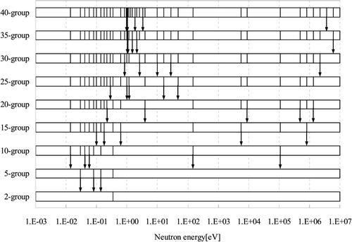
Figure 10. Energy group structure obtained by the successive collapsing method in Low-High geometry.

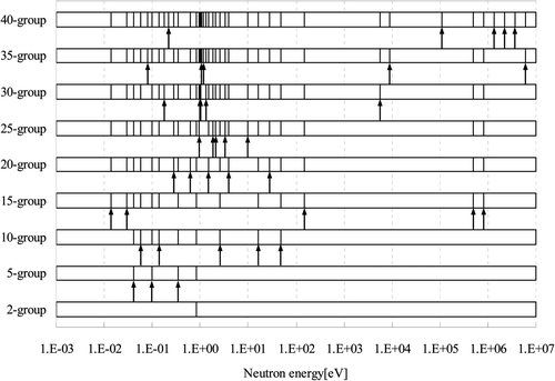
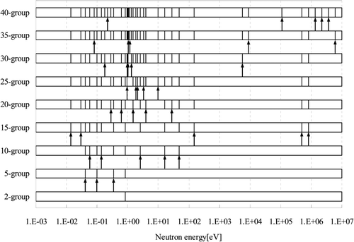
Figure 11. Energy group structure obtained by the successive expanding method in Low-High geometry.

Figure 11. Energy group structure obtained by the successive expanding method in Low-High geometry.

Figure 12. Energy group structure obtained by the successive collapsing method in Low-MOX geometry.

Figure 12. Energy group structure obtained by the successive collapsing method in Low-MOX geometry.

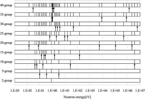
Figure 13. Energy group structure obtained by the successive expanding method in Low-MOX geometry.

Figure 13. Energy group structure obtained by the successive expanding method in Low-MOX geometry.

Figure 14. Energy group structure obtained by the successive collapsing method in High-MOX geometry.
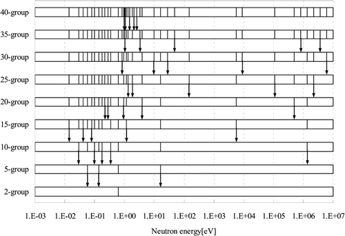
Figure 14. Energy group structure obtained by the successive collapsing method in High-MOX geometry.

Figure 15. Energy group structure obtained by the successive expanding method in High-MOX geometry.

Figure 15. Energy group structure obtained by the successive expanding method in High-MOX geometry.

Figure 16. Difference of k-infinity and pin-by-pin fission rate distribution in Low-High geometry using the energy group structures obtained with various numbers of candidates.
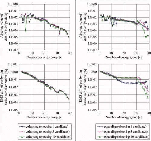
Figure 16. Difference of k-infinity and pin-by-pin fission rate distribution in Low-High geometry using the energy group structures obtained with various numbers of candidates.

Figure 17. Difference of k-infinity and pin-by-pin fission rate distribution in Low-MOX geometry using the energy group structures obtained with various numbers of candidates.
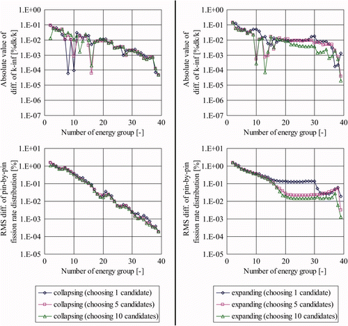
Figure 17. Difference of k-infinity and pin-by-pin fission rate distribution in Low-MOX geometry using the energy group structures obtained with various numbers of candidates.

Figure 18. Difference of k-infinity and pin-by-pin fission rate distribution in High-MOX geometry using the energy group structures obtained with various numbers of candidates.
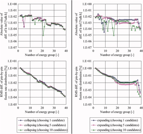
Figure 18. Difference of k-infinity and pin-by-pin fission rate distribution in High-MOX geometry using the energy group structures obtained with various numbers of candidates.

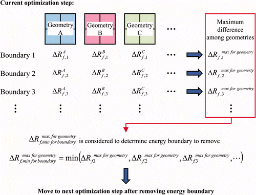
Figure 19. Concept of simultaneous application of the present approach for various configurations.

Figure 19. Concept of simultaneous application of the present approach for various configurations.

Figure 21. Difference of k-infinity and pin-by-pin fission rate distribution in multi-assemblies geometry using the energy group structures obtained by the successive collapsing method (simultaneously applied in 63 configurations).
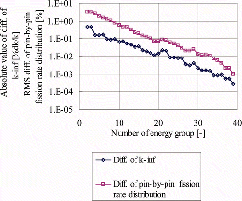
Figure 21. Difference of k-infinity and pin-by-pin fission rate distribution in multi-assemblies geometry using the energy group structures obtained by the successive collapsing method (simultaneously applied in 63 configurations).
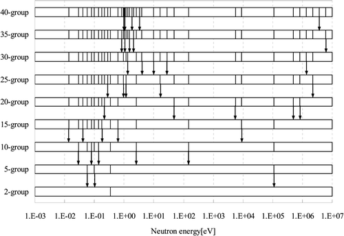
Table 1. Differences of k-infinity and pin-by-pin fission rate distribution for various energy group structures obtained in the process of the successive collapsing method.

Table 2. Energy group structures determined by the successive collapsing method.

Figure 20. Energy group structures obtained by the successive collapsing method (simultaneously applied in 63 configurations).

Figure 20. Energy group structures obtained by the successive collapsing method (simultaneously applied in 63 configurations).

Figure 22. Differences of k-infinity and pin-by-pin fission rate obtained with the determined 2-, 5-, 8-, and 15-group energy structures.
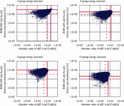
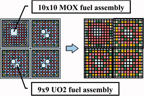
Figure 22. Differences of k-infinity and pin-by-pin fission rate obtained with the determined 2-, 5-, 8-, and 15-group energy structures.
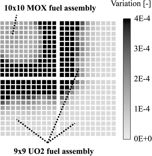
Table 3. Average values and maximum values of differences of k-infinity and pin-by-pin fission rate distribution in the verification calculation.

Table 4. 8-group structures determined in the present study and that used in the previous study.

Table 5. Average values and maximum values of differences of k-infinity and pin-by-pin fission rate distribution in the 8-group calculations.

Reprints and Corporate Permissions

Please note: Selecting permissions does not provide access to the full text of the article, please see our help page How do I view content?

To request a reprint or corporate permissions for this article, please click on the relevant link below:

Academic Permissions

Please note: Selecting permissions does not provide access to the full text of the article, please see our help page How do I view content?

Obtain permissions instantly via Rightslink by clicking on the button below:

If you are unable to obtain permissions via Rightslink, please complete and submit this Permissions form. For more information, please visit our Permissions help page.