Figures & data
Figure 2. Schematic diagram of remote calibration using transfer standard sources. The National Institute of Advanced Industrial Science and Technology calibrates transfer standard sources before sending them to users. The standard sources are measured using an ionization chamber and/or radioisotope calibrator via the Internet, and measured data are also transferred to AIST via the Internet. The calibration coefficient is calculated using the measured activity and the activity of the standard source. For the case in which the ionization current is obtained, the sensitivity is calculated using the measured current and the activity of the standard source.
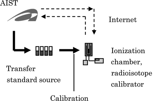
Figure 3. Plastic container and lead shield for a standard source. A standard source is stored in a plastic container with inner plastic cushions on both the top and the bottom. A piece of cushion paper is sandwiched between the standard source and an inner plastic cushion. The plastic container is placed in a lead shield, and lead shields are placed into a metal container along with inner plastic cushions.
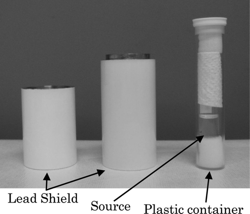
Figure 4. Schematic diagram of remote calibration using transfer equipment. The radioactive source produced on-site is calibrated remotely using transfer standard equipment, i.e., a transfer radioisotope calibrator. The calibrated source is measured using the radioisotope calibrator of interest, and the calibration coefficient is calculated using the measured activity.
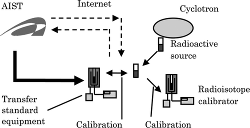
Table 1. Remote calibration experiment between AIST and JRIA using a transfer standard source.
Figure 5. Schematic diagram of the conventional calibration experiment at NMCC. The activities of radioactive sources were determined using an AIST standard ionization chamber. An ionization chamber of the secondary standard and radioisotope calibrators were calibrated.
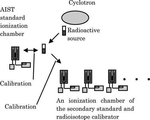
Figure 6. Schematic diagram of the conventional calibration experiment at NIRS and JRIA. The activities of radioactive sources were determined using AIST transfer standard equipment. Radioisotope calibrators at NIRS and ionization chambers of the secondary standard at JRIA were calibrated. In order to simulate the delivery of [18F]FDG to hospitals, [18F]FDG was sent to JRIA and measured at JRIA.
![Figure 6. Schematic diagram of the conventional calibration experiment at NIRS and JRIA. The activities of radioactive sources were determined using AIST transfer standard equipment. Radioisotope calibrators at NIRS and ionization chambers of the secondary standard at JRIA were calibrated. In order to simulate the delivery of [18F]FDG to hospitals, [18F]FDG was sent to JRIA and measured at JRIA.](/cms/asset/246313a3-38e0-483c-ab90-517b00bac780/tnst_a_703947_o_f0006g.gif)
Figure 7. Schematic diagram of the remote calibration experiment at NMCC. The radioactive source produced at NMCC was calibrated remotely using AIST transfer standard equipment. The calibration coefficients of the NMCC radioisotope calibrators were then obtained based on the activity of the source and indicated values of the radioisotope calibrators.
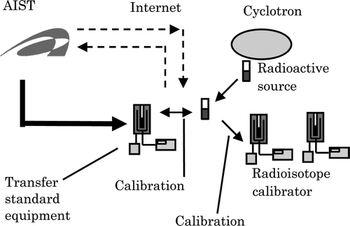
Figure 8. Calibration coefficients of ionization chambers and radioisotope calibrators using [18F] FDG. Data (A–F) show the results of the conventional method experiment at NMCC, and data (I–L) show the results of the conventional method experiment at NIRS and JRIA. The experiment at NMCC was conducted in order to calibrate radioisotope calibrators and an ionization chamber of the secondary standard using an AIST standard ionization chamber. The experiment at NIRS and JRIA was conducted in order to prepare remote calibration experiments in hospitals. In order to simulate the delivery of [18F]FDG to hospitals, [18F]FDG was sent to JRIA and measured in JRIA. Data (G–H) show the results of the remote calibration experiment between AIST and NMCC. The calibration coefficients all show that the measured activities of the ionization chambers and radioisotope calibrators were equal to the activity measured by the AIST standard chamber (A) within the limits of uncertainty.
![Figure 8. Calibration coefficients of ionization chambers and radioisotope calibrators using [18F] FDG. Data (A–F) show the results of the conventional method experiment at NMCC, and data (I–L) show the results of the conventional method experiment at NIRS and JRIA. The experiment at NMCC was conducted in order to calibrate radioisotope calibrators and an ionization chamber of the secondary standard using an AIST standard ionization chamber. The experiment at NIRS and JRIA was conducted in order to prepare remote calibration experiments in hospitals. In order to simulate the delivery of [18F]FDG to hospitals, [18F]FDG was sent to JRIA and measured in JRIA. Data (G–H) show the results of the remote calibration experiment between AIST and NMCC. The calibration coefficients all show that the measured activities of the ionization chambers and radioisotope calibrators were equal to the activity measured by the AIST standard chamber (A) within the limits of uncertainty.](/cms/asset/4cc0280a-866b-45b9-b9be-b9bfdf5938eb/tnst_a_703947_o_f0008g.gif)
