367
Views
6
CrossRef citations to date
0
Altmetric
ARTICLES

Low dose exposure diagnosis with a transXend detector aiming for iodine-marked cancer detection

, , , , , , , & show all
Pages 937-946 | Received 26 Mar 2012, Accepted 10 Jul 2012, Published online: 21 Aug 2012

Figures & data

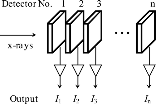
Figure 1. Schematic drawing of a transXend detector.

Figure 1. Schematic drawing of a transXend detector.

Figure 2. Calculated two-dimensional map of I 2/I 1I 3/I 1 for the cases without and with a Sn filter. The X-ray tube voltage and Sn filter thickness are 120 kV and 300 μm, respectively. The acrylic thickness is indicated in this figure. The iodine thicknesses are 0 μm (dots), 10 μm (squares), 20 μm (diamonds), 30 μm (up triangles), and 40 μm (down triangles), respectively.
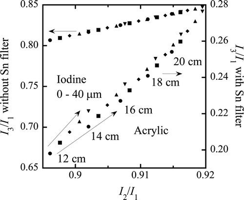
Figure 2. Calculated two-dimensional map of I 2/I 1–I 3/I 1 for the cases without and with a Sn filter. The X-ray tube voltage and Sn filter thickness are 120 kV and 300 μm, respectively. The acrylic thickness is indicated in this figure. The iodine thicknesses are 0 μm (dots), 10 μm (squares), 20 μm (diamonds), 30 μm (up triangles), and 40 μm (down triangles), respectively.

Figure 3. Experimental setup. Acrylic slabs, an acrylic with iodine regions in it, and step phantom of aluminum are employed for two-dimensional map measurements. For the scanning measurements, cylindrical phantoms in Figure 5 are used.
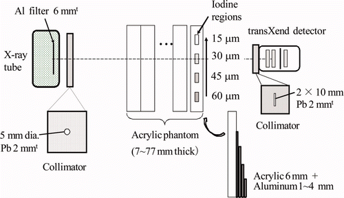
Figure 3. Experimental setup. Acrylic slabs, an acrylic with iodine regions in it, and step phantom of aluminum are employed for two-dimensional map measurements. For the scanning measurements, cylindrical phantoms in Figure 5 are used.

Figure 4. Two-dimensional map for acrylic and iodine thickness estimation. Acrylic phantom thickness ranges from 7 to 77 mm with 10 mm intervals. Iodine thickness is shown in this figure.
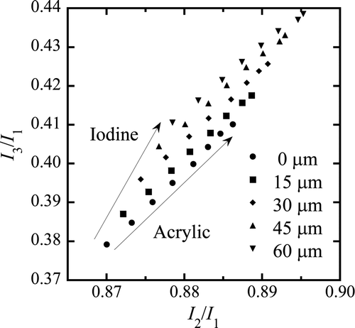
Figure 4. Two-dimensional map for acrylic and iodine thickness estimation. Acrylic phantom thickness ranges from 7 to 77 mm with 10 mm intervals. Iodine thickness is shown in this figure.

Figure 5. Schematic drawings of acrylic phantoms for (a) acrylic–iodine and (b) acrylic–iodine–aluminum thickness distribution measurements.
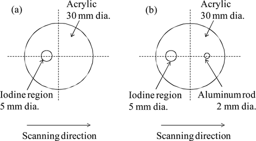
Figure 5. Schematic drawings of acrylic phantoms for (a) acrylic–iodine and (b) acrylic–iodine–aluminum thickness distribution measurements.

Figure 6. Estimated thickness distributions of acrylic and iodine. The position x = 0 means the center of cylindrical acrylic phantom. Dashed lines are the theoretical thickness distributions.
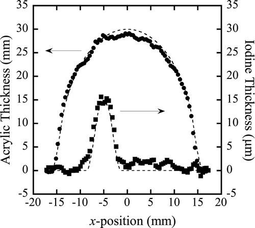
Figure 6. Estimated thickness distributions of acrylic and iodine. The position x = 0 means the center of cylindrical acrylic phantom. Dashed lines are the theoretical thickness distributions.

Figure 7. Two-dimensional maps for (a) acrylic–iodine and (b) acrylic–aluminum thickness distribution estimation. “Ref.” means the reference points af described in . “Air” means the measured points without acrylic phantom. Solid lines are the scanned results for the acrylic phantom shown in Figure 5(b).
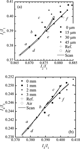
Figure 7. Two-dimensional maps for (a) acrylic–iodine and (b) acrylic–aluminum thickness distribution estimation. “Ref.” means the reference points a–f described in Table 1. “Air” means the measured points without acrylic phantom. Solid lines are the scanned results for the acrylic phantom shown in Figure 5(b).

Table 1. Reference points for the correction of hidden materials in two-dimensional maps.

Figure 8. Estimated thickness distributions for (a) acrylic (dots)–iodine (squares) and (b) acrylic (dots)–aluminum (triangles), without taking into account the effect of hidden materials.
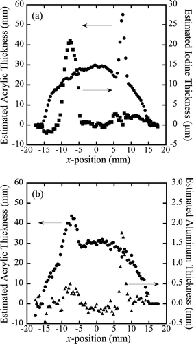
Figure 8. Estimated thickness distributions for (a) acrylic (dots)–iodine (squares) and (b) acrylic (dots)–aluminum (triangles), without taking into account the effect of hidden materials.

Figure 9. Schematics for estimating hidden materials: (a) aluminum in Figure 7(a), and (b) iodine in Figure 7(b).
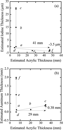
Figure 9. Schematics for estimating hidden materials: (a) aluminum in Figure 7(a), and (b) iodine in Figure 7(b).

Figure 10. Corrected thickness distributions for acrylic (dots), iodine (squares), and aluminum (triangles). Aluminum thickness 1 mm is normalized to 15 μm thick iodine for easy comparison. Dashed lines are the theoretical thickness distributions.
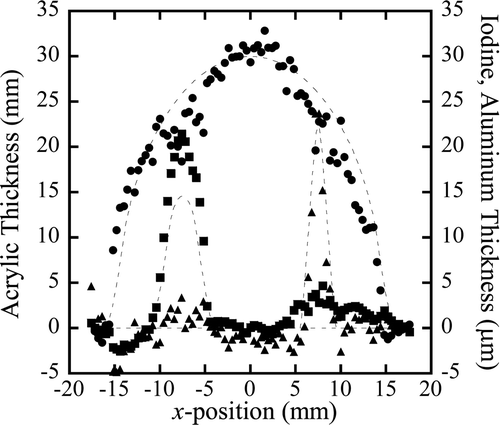
Figure 10. Corrected thickness distributions for acrylic (dots), iodine (squares), and aluminum (triangles). Aluminum thickness 1 mm is normalized to 15 μm thick iodine for easy comparison. Dashed lines are the theoretical thickness distributions.

Figure 11. Calculated number of photons deposited in (a) the first, (b) the second, and (c) the third segment detector, and (d) the third segment detector with 300 μm thick Sn filter in front of it as a function of energy. The solid, dashed, and broken lines show the photons after passing 16, 18, and 20 cm of acrylic.
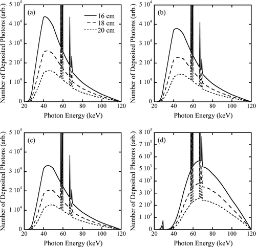
Figure 11. Calculated number of photons deposited in (a) the first, (b) the second, and (c) the third segment detector, and (d) the third segment detector with 300 μm thick Sn filter in front of it as a function of energy. The solid, dashed, and broken lines show the photons after passing 16, 18, and 20 cm of acrylic.

Figure 12. Calculated number of photons deposited in (a) the first, (b) the second, (c) the third segment detector, and (d) the third segment detector with 300 μm thick Sn filter in front of it as a function of energy. The solid, dashed, and broken lines show the photons after passing 0, 20, and 40 μm thick iodine as well as 20 cm of acrylic.
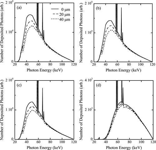
Figure 12. Calculated number of photons deposited in (a) the first, (b) the second, (c) the third segment detector, and (d) the third segment detector with 300 μm thick Sn filter in front of it as a function of energy. The solid, dashed, and broken lines show the photons after passing 0, 20, and 40 μm thick iodine as well as 20 cm of acrylic.
Reprints and Corporate Permissions

Please note: Selecting permissions does not provide access to the full text of the article, please see our help page How do I view content?

To request a reprint or corporate permissions for this article, please click on the relevant link below:

Academic Permissions

Please note: Selecting permissions does not provide access to the full text of the article, please see our help page How do I view content?

Obtain permissions instantly via Rightslink by clicking on the button below:

If you are unable to obtain permissions via Rightslink, please complete and submit this Permissions form. For more information, please visit our Permissions help page.