Figures & data
Figure 1 Schematic diagram of the mercury experimental loop
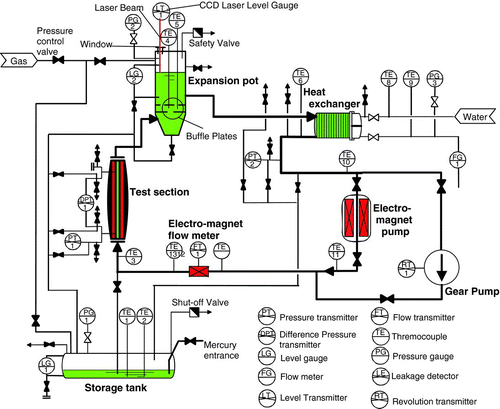
Figure 2 Schematic drawing of the test section
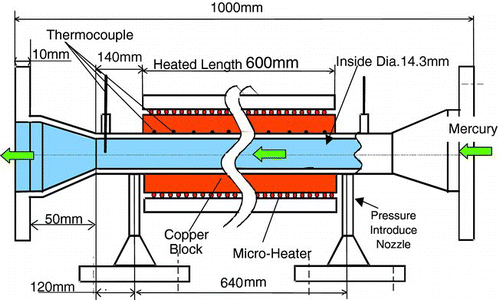
Figure 3 External view of the test section
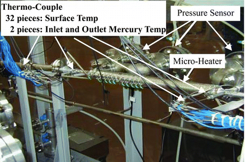
Figure 4 Relationship between pressure drop and mercury velocity
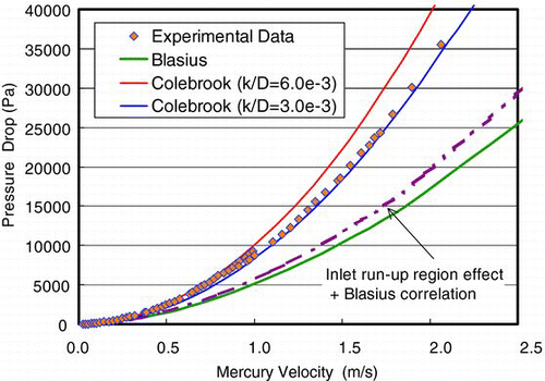
Figure 5 Relationship between friction factor and Reynolds number
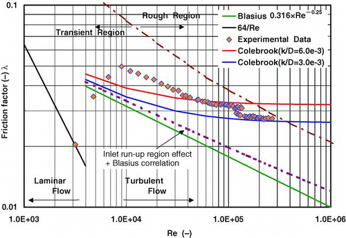
Figure 6 Roughness Reynolds number of mercury (roughness k = 35 and 85 μm)
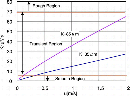
Figure 7 Relationship between heat transfer coefficient and mercury velocity
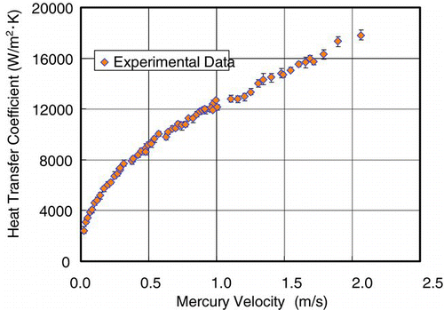
Figure 8 Experimental data and correlations expressed as relationship between Nusselt number and Peclet number
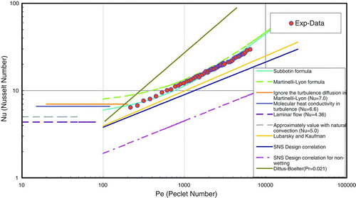
Figure 9 Analytical model for heat transfer analysis
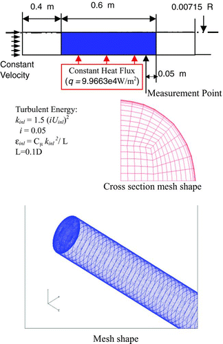
Table 1 y+ value for Reynolds number
Figure 10 Comparison with experimental and analytical results of friction factor
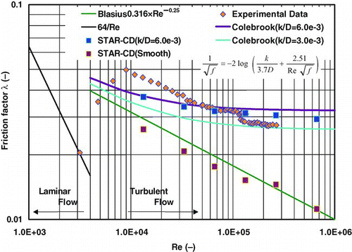
Figure 11 Comparison with experimental data, analytical results and correlations expressed as relationship between Nusselt number and Peclet number
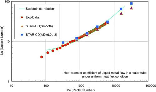
Figure 12 Temperature distribution of the 3-D analysis
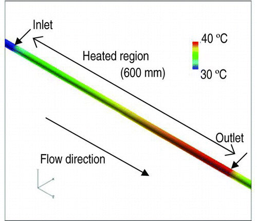
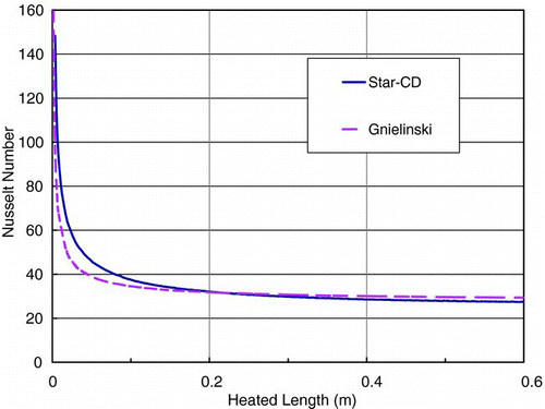
Figure 13 Heat transfer coefficient distribution of the 3-D analysis
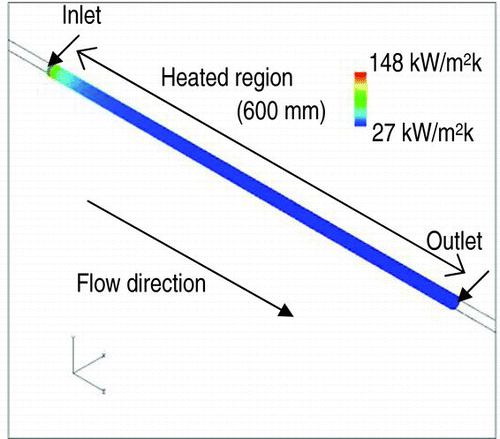
Figure 14 Heat transfer coefficient along with flow direction