2,571
Views
32
CrossRef citations to date
0
Altmetric
50th ANNIVERSARY INVITED REVIEW

Evolution of the ITER program and prospect for the next-step fusion DEMO reactors: status of the fusion energy R&D as ultimate source of energy

&
Pages 321-345 | Received 02 Oct 2012, Accepted 08 Jan 2013, Published online: 28 Mar 2013

Figures & data

Figure 1 Tokamak-type fusion power plant concept and the definition of energy multiplication factor Q
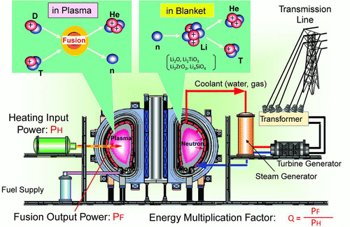
Figure 1 Tokamak-type fusion power plant concept and the definition of energy multiplication factor Q

Figure 2 Progress of the plasma performance toward fusion reactors in the nτ– T diagram, where n is plasma ion density, τ is energy confinement time, and T is ion temperature
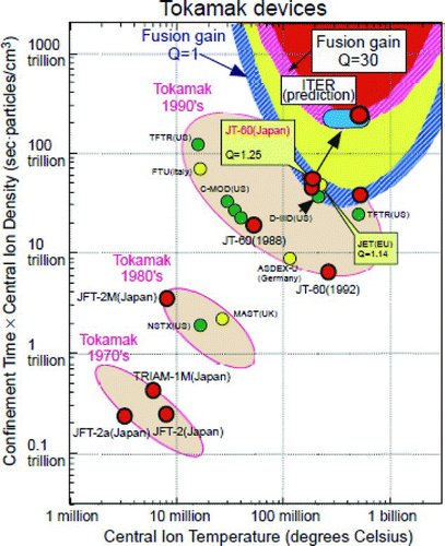
Figure 2 Progress of the plasma performance toward fusion reactors in the nτ– T diagram, where n is plasma ion density, τ is energy confinement time, and T is ion temperature

Figure 3 ITER preparatory activities before construction

Figure 3 ITER preparatory activities before construction

Table 1 Typical machine parameters of the ITER-CDA, ITER-FDR, and ITER-FEAT

Figure 4 Empirical scaling law obtained by the collaboration of the integrated work done by the ITPA (ITER Physics Activity) group
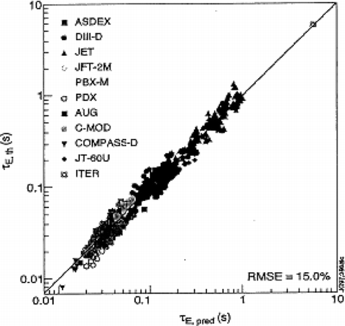
Figure 4 Empirical scaling law obtained by the collaboration of the integrated work done by the ITPA (ITER Physics Activity) group

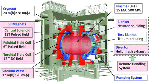
Figure 5 A bird-eye view of the ITER core component and typical dimensions

Figure 5 A bird-eye view of the ITER core component and typical dimensions

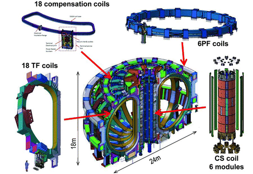
Figure 6 ITER superconducting magnet configuration and their numbers

Figure 6 ITER superconducting magnet configuration and their numbers

Table 2 Major parameters of the ITER superconducting magnet system

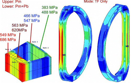
Figure 7 Mechanical stress due to electromagnetic forces by the TF coils

Figure 7 Mechanical stress due to electromagnetic forces by the TF coils

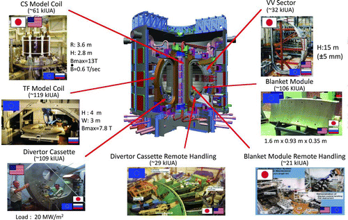
Figure 8 Seven large R&D projects performed in the ITER EDA

Figure 8 Seven large R&D projects performed in the ITER EDA

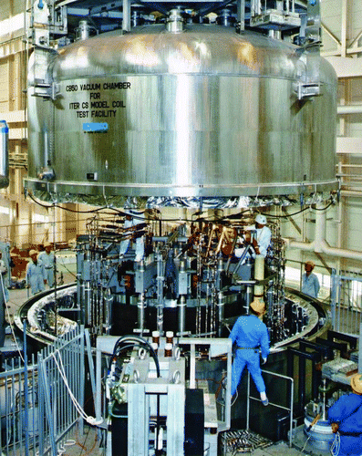
Figure 9 Central model coil assembled in the test facility at the JAERI

Figure 9 Central model coil assembled in the test facility at the JAERI

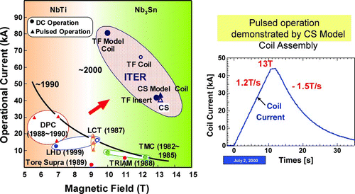
Figure 10 Breakthrough in the superconducting magnet technology by the ITER R&D

Figure 10 Breakthrough in the superconducting magnet technology by the ITER R&D

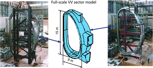
Figure 11 Vacuum vessel sector R&D: two segments were field-welded

Figure 11 Vacuum vessel sector R&D: two segments were field-welded

Figure 12 Divertor cassette and target element under test in the international collaboration. Photos provided by ITER Organization
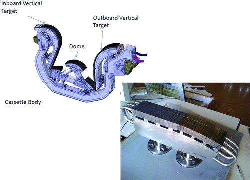
Figure 12 Divertor cassette and target element under test in the international collaboration. Photos provided by ITER Organization

Figure 13 Design concept (right) and R&D (left) of the blanket remote maintenance equipment. Photos provided by ITER Organization
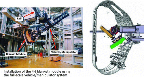
Figure 13 Design concept (right) and R&D (left) of the blanket remote maintenance equipment. Photos provided by ITER Organization

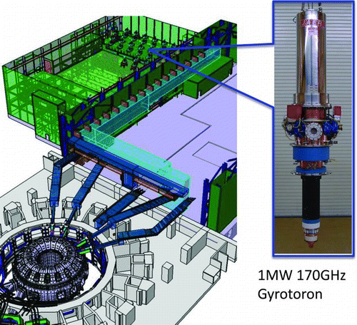
Figure 14 Developed 1-MW 170-GHz Gyratoron at the JAEA and the layout for ITER application

Figure 14 Developed 1-MW 170-GHz Gyratoron at the JAEA and the layout for ITER application

Figure 15 ITER main office building near completion and the working area in the completed PF coil assembly building (photos provided by ITER Organization)
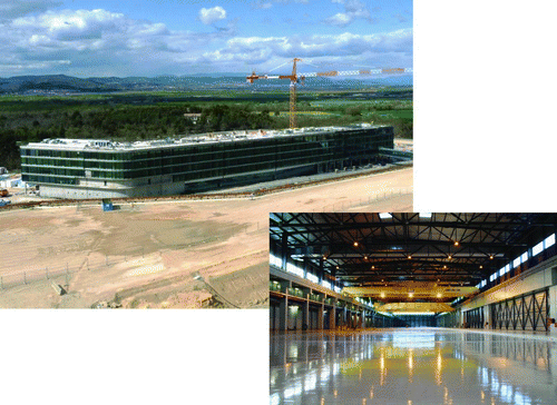
Figure 15 ITER main office building near completion and the working area in the completed PF coil assembly building (photos provided by ITER Organization)

Figure 16 The groundwork for the Tokamak complex building is in progress and about 500 antiseismic bearing structures have been installed in the pit (photos provided by ITER Organization)
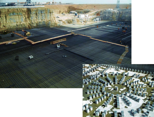
Figure 16 The groundwork for the Tokamak complex building is in progress and about 500 antiseismic bearing structures have been installed in the pit (photos provided by ITER Organization)

Figure 17 ITER cable in conduit conductors. Note: The superconducting cable is inserted in a metal conduit whose outer shape is rectangular (for CS and PF) or circular (for TF). Several hundreds of strands, each containing about 10,000 Nb filaments of a few micrometers, are twisted and pulled in a metal conduit of about 3 cm diameter
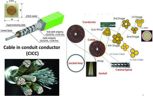
Figure 17 ITER cable in conduit conductors. Note: The superconducting cable is inserted in a metal conduit whose outer shape is rectangular (for CS and PF) or circular (for TF). Several hundreds of strands, each containing about 10,000 Nb filaments of a few micrometers, are twisted and pulled in a metal conduit of about 3 cm diameter

Figure 18 Superconducting cable fabrication facility at the Shin-Nittetsu Engineering Works and the produced conductors wound on a bobbin (lower photos)
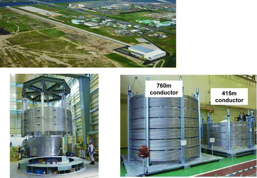
Figure 18 Superconducting cable fabrication facility at the Shin-Nittetsu Engineering Works and the produced conductors wound on a bobbin (lower photos)

Figure 19 TF conductor winding line at the European vendor ASG Superconductors showing a first full-size turn for demonstration (ASG Superconductors copyright)
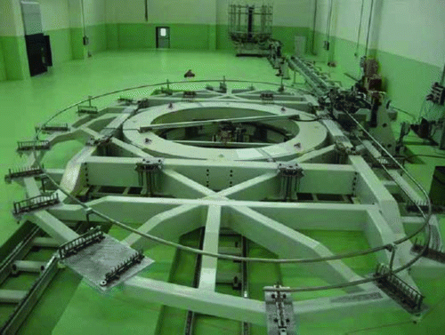
Figure 19 TF conductor winding line at the European vendor ASG Superconductors showing a first full-size turn for demonstration (ASG Superconductors copyright)

Figure 20 Trial fabrication of the TF coil casing steel block. Note: The JJ1, ST316LN, and SS316LN are developed for high performance at cryogenic temperatures
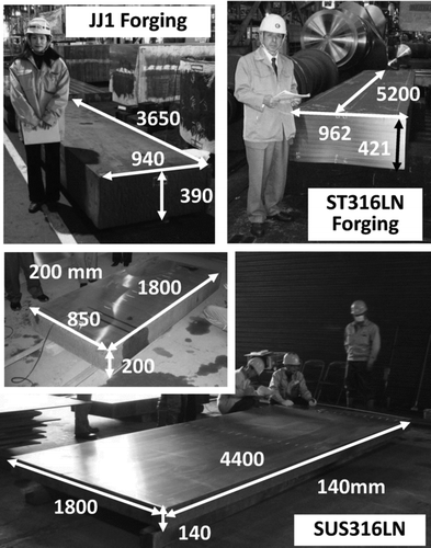
Figure 20 Trial fabrication of the TF coil casing steel block. Note: The JJ1, ST316LN, and SS316LN are developed for high performance at cryogenic temperatures

Figure 21 Mock-up fabrication of the vacuum vessel segments by Hyundai Heavy Industries (provided by Korean Domestic Agency)
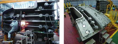
Figure 21 Mock-up fabrication of the vacuum vessel segments by Hyundai Heavy Industries (provided by Korean Domestic Agency)

Figure 22 Integration of elements toward DEMO reactor. Note: The ITER integrates most of the plasma physics and technologies, but the blanket technologies and the advanced plasma development have to be incorporated into DEMO reactors
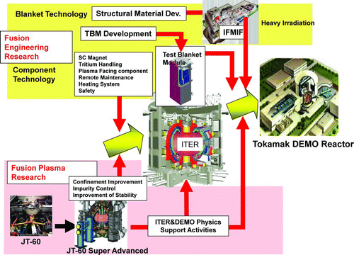
Figure 22 Integration of elements toward DEMO reactor. Note: The ITER integrates most of the plasma physics and technologies, but the blanket technologies and the advanced plasma development have to be incorporated into DEMO reactors

Table 3 Comparison of fusion reactors aiming at high-power output densities

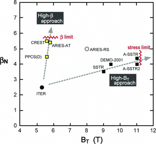
Figure 23 Typical fusion reactor designs have two trends: a high B T approach and a high β approach

Figure 23 Typical fusion reactor designs have two trends: a high B T approach and a high β approach

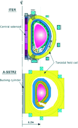
Figure 24 A comparison of the cross-section of ITER and A-SSTR2 (DEMO) TF coils

Figure 24 A comparison of the cross-section of ITER and A-SSTR2 (DEMO) TF coils

Figure 25 Cross-section of the plasma in the typical designs with an envelop of an output of 3 GW and a neutron wall loading of 3 MWm−2
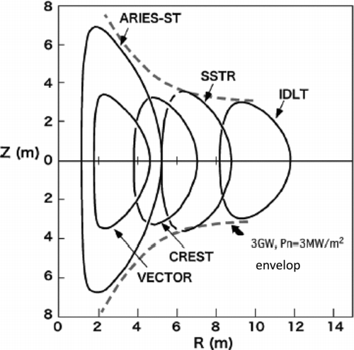
Figure 25 Cross-section of the plasma in the typical designs with an envelop of an output of 3 GW and a neutron wall loading of 3 MWm−2

Table 4 Several types of blanket for power reactors to be tested in the ITER TBM

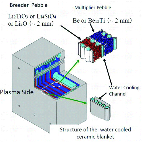
Figure 26 One of the blanket concepts, a water cooled ceramic breeder

Figure 26 One of the blanket concepts, a water cooled ceramic breeder

Figure 27 Test sample of the ferritic steel (F82H) first wall with cooling channels made by the HIP bonding technique
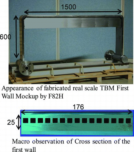
Figure 27 Test sample of the ferritic steel (F82H) first wall with cooling channels made by the HIP bonding technique

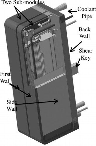
Figure 28 Configuration of the water-cooled TBM by Japan

Figure 28 Configuration of the water-cooled TBM by Japan

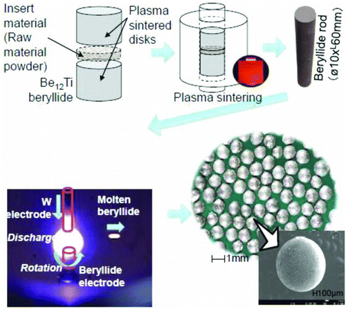
Figure 29 A new production method under development on the Be-Ti pebble

Figure 29 A new production method under development on the Be-Ti pebble

Figure 30 Heavy neutron irradiation tests already done, ongoing, and the plan for higher irradiation for F82H and for SiC/SiC materials at various temperatures by the fission materials test reactor
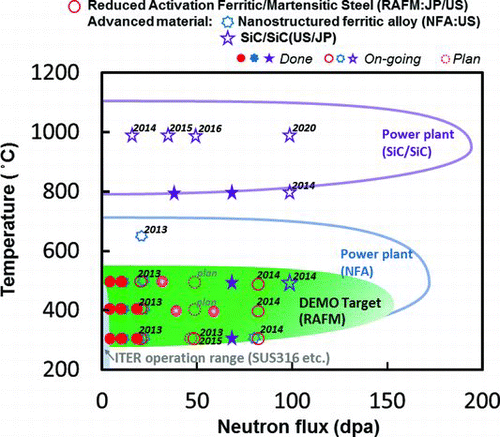
Figure 30 Heavy neutron irradiation tests already done, ongoing, and the plan for higher irradiation for F82H and for SiC/SiC materials at various temperatures by the fission materials test reactor

Figure 31 Bird's eye view of the IFMIF (International Fusion Materials Irradiation Facility) as presented in the Comprehensive Design Report [Citation25]

Figure 31 Bird's eye view of the IFMIF (International Fusion Materials Irradiation Facility) as presented in the Comprehensive Design Report [Citation25]

Figure 32 Target design value of the IFMIF accelerator, lithium target, and the test cell

Figure 32 Target design value of the IFMIF accelerator, lithium target, and the test cell

Figure 33 The Rokkasyo International Fusion Energy Research Center and the IFMIF/ EVEDA building (right) waiting for prototype accelerator tests
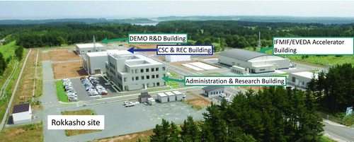
Figure 33 The Rokkasyo International Fusion Energy Research Center and the IFMIF/ EVEDA building (right) waiting for prototype accelerator tests

Figure 34 Liquid lithium loop facility for IFMIF at the JAEA Oarai to confirm stable free-boundary flow and purification
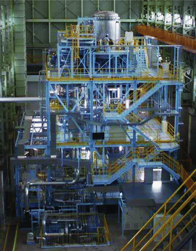
Figure 34 Liquid lithium loop facility for IFMIF at the JAEA Oarai to confirm stable free-boundary flow and purification

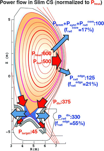
Figure 35 Power flow from the reactor core plasma to the divertor

Figure 35 Power flow from the reactor core plasma to the divertor

Figure 36 Sector blanket concept developed by the JAEA. Note: The EU has developed a concept to take out the module from the top of the tokamak
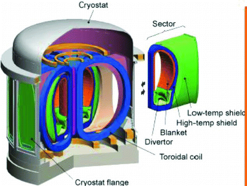
Figure 36 Sector blanket concept developed by the JAEA. Note: The EU has developed a concept to take out the module from the top of the tokamak
Reprints and Corporate Permissions

Please note: Selecting permissions does not provide access to the full text of the article, please see our help page How do I view content?

To request a reprint or corporate permissions for this article, please click on the relevant link below:

Academic Permissions

Please note: Selecting permissions does not provide access to the full text of the article, please see our help page How do I view content?

Obtain permissions instantly via Rightslink by clicking on the button below:

If you are unable to obtain permissions via Rightslink, please complete and submit this Permissions form. For more information, please visit our Permissions help page.