1,035
Views
8
CrossRef citations to date
0
Altmetric
Article

Simulation of the fracture behavior of Zircaloy-4 cladding under reactivity-initiated accident conditions with a damage mechanics model combined with fuel performance codes FEMAXI-7 and RANNS

, , , &
Pages 208-219 | Received 09 Sep 2013, Accepted 21 Oct 2013, Published online: 15 Nov 2013

Figures & data

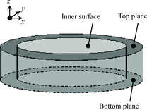
Figure 1. An elevation of the cladding tube model.

Figure 1. An elevation of the cladding tube model.

Table 1. Damage model parameters.

Figure 2. FEM models of the cladding tube: (a) horizontal cross section, (b) vertical cross section, (c) geometry of the damage region for smooth specimens, and (d) geometry of the damage region for pre-cracked specimens.
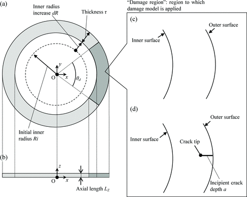
Figure 2. FEM models of the cladding tube: (a) horizontal cross section, (b) vertical cross section, (c) geometry of the damage region for smooth specimens, and (d) geometry of the damage region for pre-cracked specimens.

Figure 3. Fracture appearances of a smooth specimen in the simulated burst test at 300 K.

Figure 3. Fracture appearances of a smooth specimen in the simulated burst test at 300 K.

Figure 4. Simulation results of the RAG–EDC test: (a) outer surface strain at failure compared with experimental results and (b) fracture appearances of pre-cracked specimens.
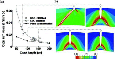
Figure 4. Simulation results of the RAG–EDC test: (a) outer surface strain at failure compared with experimental results and (b) fracture appearances of pre-cracked specimens.

Figure 5. Hoop strains calculated under different stress states around the tip of a 100-μm crack in a wall of 570 μm thickness: (a) hoop strain distributions at ϵm,θ = 2% and (b) variations of strain concentration with increasing hoop strain ϵm,θ.
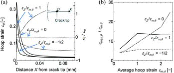
Figure 5. Hoop strains calculated under different stress states around the tip of a 100-μm crack in a wall of 570 μm thickness: (a) hoop strain distributions at ϵm,θ = 2% and (b) variations of strain concentration with increasing hoop strain ϵm,θ.

Figure 6. Sensitivity of failure strains at 300 K to the damage parameters and : (a) residual hoop strains calculated in the burst test analysis and (b) outer surface hoop strains at failure calculated in the RAG–EDC test analysis.
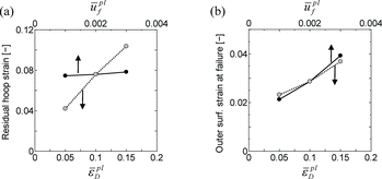
Figure 6. Sensitivity of failure strains at 300 K to the damage parameters and : (a) residual hoop strains calculated in the burst test analysis and (b) outer surface hoop strains at failure calculated in the RAG–EDC test analysis.

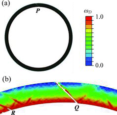
Figure 7. Fracture appearances of the claddings in the NSRR tests L6 and H6: horizontal cross sections of the fuel cladding around the fracture positions.
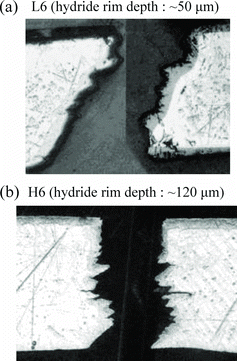
Figure 7. Fracture appearances of the claddings in the NSRR tests L6 and H6: horizontal cross sections of the fuel cladding around the fracture positions.

Table 2. Summary of the RANNS calculation conditions.

Figure 8. Evolution of (a) axial stress with increasing hoop stress and (b) axial strain with increasing hoop strain in the cladding periphery.
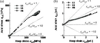
Figure 8. Evolution of (a) axial stress with increasing hoop stress and (b) axial strain with increasing hoop strain in the cladding periphery.

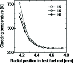
Figure 9. Radial temperature profiles in the cladding wall at failure time.

Figure 9. Radial temperature profiles in the cladding wall at failure time.

Figure 10. Cladding inner surface strains at failure calculated with the damage model compared to the NSRR test results.
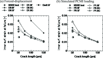
Figure 10. Cladding inner surface strains at failure calculated with the damage model compared to the NSRR test results.

Figure 11. Simulated fracture appearances of the pre-cracked claddings in cases D0.0F, D1.0F, and P0.0F.
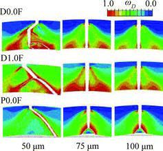
Figure 11. Simulated fracture appearances of the pre-cracked claddings in cases D0.0F, D1.0F, and P0.0F.

Figure 12. Simulated crack propagation in case P0.0F. Through-wall penetration by a crack is achieved with very a small strain increment.
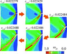
Figure 12. Simulated crack propagation in case P0.0F. Through-wall penetration by a crack is achieved with very a small strain increment.

Figure 13. Evolutions of the state variables ωD and D at the tip of a 50-μm crack with increasing cladding inner radius, in the cases D0.0F and D1.0F.
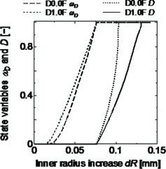
Figure 13. Evolutions of the state variables ωD and D at the tip of a 50-μm crack with increasing cladding inner radius, in the cases D0.0F and D1.0F.
Reprints and Corporate Permissions

Please note: Selecting permissions does not provide access to the full text of the article, please see our help page How do I view content?

To request a reprint or corporate permissions for this article, please click on the relevant link below:

Academic Permissions

Please note: Selecting permissions does not provide access to the full text of the article, please see our help page How do I view content?

Obtain permissions instantly via Rightslink by clicking on the button below:

If you are unable to obtain permissions via Rightslink, please complete and submit this Permissions form. For more information, please visit our Permissions help page.