2,302
Views
7
CrossRef citations to date
0
Altmetric
Technical Material

Steam generator small bore piping socket weld inspection using the phased array ultrasonic technique

, &
Pages 231-239 | Received 24 Jun 2013, Accepted 06 Oct 2013, Published online: 08 Nov 2013

Figures & data

Figure 1. Phased array ultrasonic technology generating multi-angle ultrasonic.

Figure 1. Phased array ultrasonic technology generating multi-angle ultrasonic.

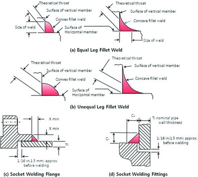
Figure 2. Socket weld configuration (ASME Section III 4542.9-1).

Figure 2. Socket weld configuration (ASME Section III 4542.9-1).

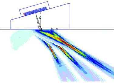
Figure 3. Ultrasonic sound field modeling results at (a) 45° and (b) 80° refraction angles at a 0.4-mm pitch.
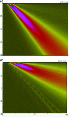
Figure 3. Ultrasonic sound field modeling results at (a) 45° and (b) 80° refraction angles at a 0.4-mm pitch.

Table 1. Phased array probe and wedge specifications.

Figure 4. Phased array ultrasonic transducer and wedge for SG small bore piping socket weld inspection.
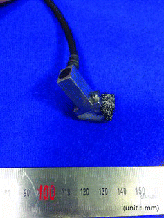
Figure 4. Phased array ultrasonic transducer and wedge for SG small bore piping socket weld inspection.

Figure 5. Manually operated ring-type encoded scanner for the small bore socket weld piping of steam generators.
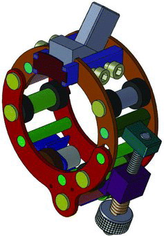
Figure 5. Manually operated ring-type encoded scanner for the small bore socket weld piping of steam generators.

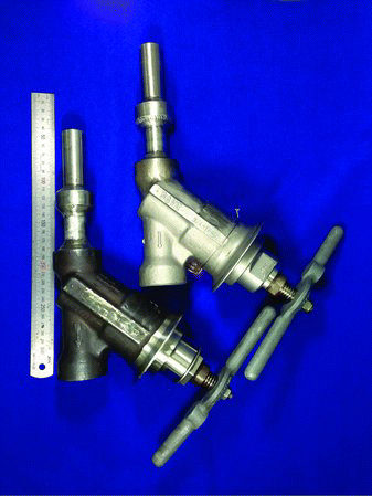
Figure 6. Manufactured flawed specimen of SG drain line socket weld.

Figure 6. Manufactured flawed specimen of SG drain line socket weld.

Table 2. Flaws introduced to specimens (unit: mm).

Figure 7. Experimental configuration of the phased array ultrasonic system.

Figure 7. Experimental configuration of the phased array ultrasonic system.

Table 3. Phased array system parameters for experimental.

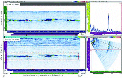
Figure 8. Signals from the valve side weld of flawed specimens with 1:1 leg length ratio.

Figure 8. Signals from the valve side weld of flawed specimens with 1:1 leg length ratio.

Figure 9. Valve side weld signal of flawed specimens with 1:2 leg length ratio.

Figure 9. Valve side weld signal of flawed specimens with 1:2 leg length ratio.

Table 4. Flaw length sizing results of flawed specimens (unit: mm).

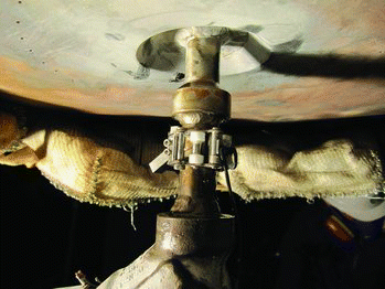
Figure 10. SG drain pipe socket weld inspection.

Figure 10. SG drain pipe socket weld inspection.

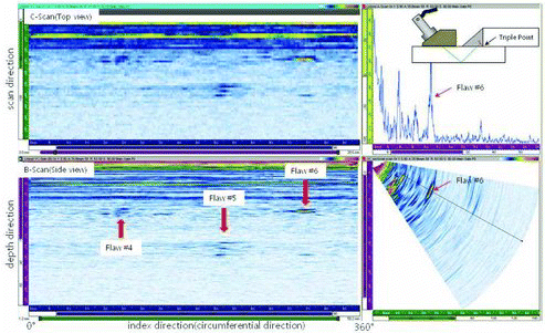
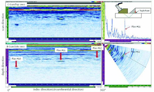
Figure 11. SG “A” drain line valve socket weld inspection result.

Figure 11. SG “A” drain line valve socket weld inspection result.

Reprints and Corporate Permissions

Please note: Selecting permissions does not provide access to the full text of the article, please see our help page How do I view content?

To request a reprint or corporate permissions for this article, please click on the relevant link below:

Academic Permissions

Please note: Selecting permissions does not provide access to the full text of the article, please see our help page How do I view content?

Obtain permissions instantly via Rightslink by clicking on the button below:

If you are unable to obtain permissions via Rightslink, please complete and submit this Permissions form. For more information, please visit our Permissions help page.