1,323
Views
3
CrossRef citations to date
0
Altmetric
Technical Material

Design features and thermal margin assessment of core protection and monitoring systems of an integral reactor, SMART

, , &
Pages 390-404 | Received 11 Jun 2013, Accepted 05 Nov 2013, Published online: 29 Nov 2013

Figures & data

Table 1. Primary design parameters of SMART.

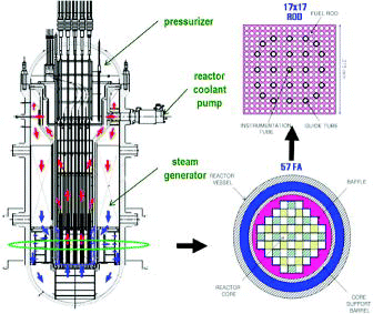
Figure 1. SMART core configuration. Source: Author.

Figure 1. SMART core configuration. Source: Author.

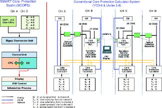
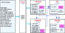
Figure 2. SCOPS hardware configuration. Source: Author.

Figure 2. SCOPS hardware configuration. Source: Author.

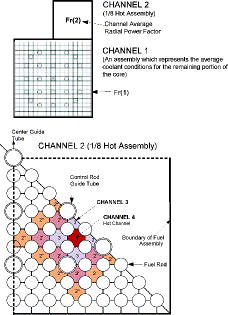
Figure 3. SCOPS and SCOMS DNBR channel model. Source: Author.

Figure 3. SCOPS and SCOMS DNBR channel model. Source: Author.

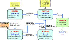
Figure 4. Interfaces between SCOPS modules. Source: Author.

Figure 4. Interfaces between SCOPS modules. Source: Author.

Figure 5. Interfaces between SCOMS modules. Source: Author.

Figure 5. Interfaces between SCOMS modules. Source: Author.

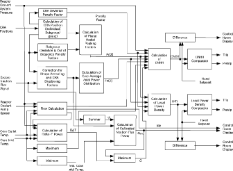
Figure 6. Functional diagram of the SCOPS algorithm. Source: Author.

Figure 6. Functional diagram of the SCOPS algorithm. Source: Author.

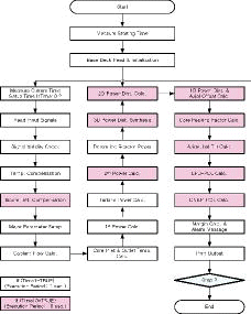
Figure 7. Flowchart of the SCOMS algorithm. Source: Author.

Figure 7. Flowchart of the SCOMS algorithm. Source: Author.

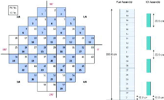
Figure 8. Simulated incore detector configuration and installed position. Source: Author.

Figure 8. Simulated incore detector configuration and installed position. Source: Author.

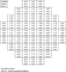
Figure 9. Axially integrated power distribution of the SMART initial core (BOC). Source: Author.

Figure 9. Axially integrated power distribution of the SMART initial core (BOC). Source: Author.

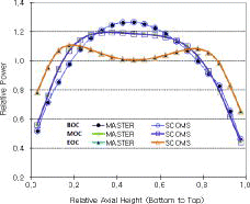
Figure 10. Axial power distributions of the SMART initial core (BOC-EOC). Source: Author.

Figure 10. Axial power distributions of the SMART initial core (BOC-EOC). Source: Author.

Table 2. 3D power distribution synthesis errors as a function of the number of failed detectors.

Table 3. Failed detector information for 3D power synthesis error calculation.

Table 4. Uncertainty components used in uncertainty analysis.

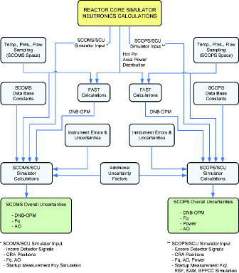
Figure 11. Systematic diagram for uncertainty analysis. Source: Author.

Figure 11. Systematic diagram for uncertainty analysis. Source: Author.

Table 5. Individual uncertainties for overall uncertainty factors of SCOPS.

Table 6. Individual uncertainties for overall uncertainty factors of SCOMS.

Table 7. SCOPS overall uncertainty factors of the SMART initial core.

Table 8. SCOMS overall uncertainty factors of the SMART initial core.

Table 9. SCOPS LPD overpower margin of the SMART initial core.

Table 10. SCOPS DNBR overpower margin of the SMART initial core.

Table 11. SCOMS LPD overpower margin of the SMART initial core.

Table 12. SCOMS DNBR overpower margin of the SMART initial core.

Reprints and Corporate Permissions

Please note: Selecting permissions does not provide access to the full text of the article, please see our help page How do I view content?

To request a reprint or corporate permissions for this article, please click on the relevant link below:

Academic Permissions

Please note: Selecting permissions does not provide access to the full text of the article, please see our help page How do I view content?

Obtain permissions instantly via Rightslink by clicking on the button below:

If you are unable to obtain permissions via Rightslink, please complete and submit this Permissions form. For more information, please visit our Permissions help page.