779
Views
3
CrossRef citations to date
0
Altmetric
Article

Quantitative common cause failure modeling for auxiliary feedwater system involving the seismic-induced degradation of flood barriers

, &
Pages 332-342 | Received 06 Feb 2013, Accepted 11 Nov 2013, Published online: 09 Dec 2013

Figures & data

Figure 1. Fault tree for possible flood.

Figure 1. Fault tree for possible flood.

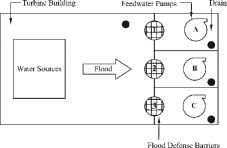
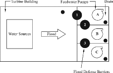
Figure 2. Additional flood barriers in turbine building as parallel Layout 1.

Figure 2. Additional flood barriers in turbine building as parallel Layout 1.

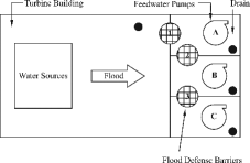
Figure 3. Additional flood barriers in turbine building as sequential Layout 2.

Figure 3. Additional flood barriers in turbine building as sequential Layout 2.

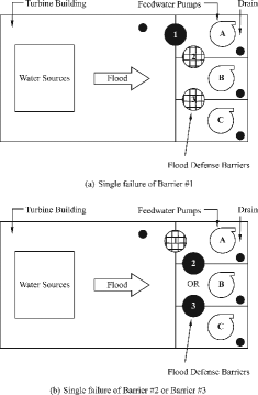
Figure 4. Seismic-induced one-barrier failure (Layout 2).

Figure 4. Seismic-induced one-barrier failure (Layout 2).

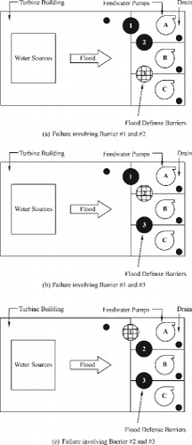
Figure 5. Seismic-induced two-barrier failure (Layout 2).

Figure 5. Seismic-induced two-barrier failure (Layout 2).

Figure 6. Seismic-induced three-barrier failure (Layout 2).

Figure 6. Seismic-induced three-barrier failure (Layout 2).

Table 1. Possible failure types for two layouts.

Table 2. Description of four Markov states.

Table 3. Description of four transition parameters.

Figure 7. Four-state Markov model for the degradation of flood barriers.

Figure 7. Four-state Markov model for the degradation of flood barriers.

Table 4. Uncertainty distribution assumption for Markov parameters.

Table 5. Assumed water flow rate through barriers for Markov states.

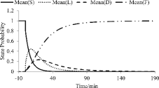
Figure 8. Time-dependent probabilities of Markov states.

Figure 8. Time-dependent probabilities of Markov states.

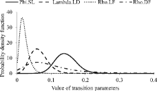
Figure 9. The posterior distributions for transition parameters in Markov model.

Figure 9. The posterior distributions for transition parameters in Markov model.

Table 6. Calculation assumption for water flow rate through a barrier.

Table 7. Hypothetical experiments with states account for the estimation of transition parameters.

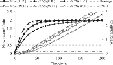
Figure 10. Water flow rate and height in AFW pump rooms (Layout 1).

Figure 10. Water flow rate and height in AFW pump rooms (Layout 1).

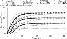
Figure 11. Water flow rate though flood barriers (Layout 2).

Figure 11. Water flow rate though flood barriers (Layout 2).

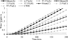
Figure 12. Water height in AFW pump rooms (Layout 2).

Figure 12. Water height in AFW pump rooms (Layout 2).

Figure 13. Time-dependent failure probability percentage (Layout 1).

Figure 13. Time-dependent failure probability percentage (Layout 1).

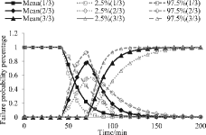
Figure 14. Time-dependent failure probability percentage (Layout 2).

Figure 14. Time-dependent failure probability percentage (Layout 2).

Table 8. Hypothetical flow rate of flood water sources.

Table 9. Failure probability distributions for different scenarios.

Table 10. The estimated decomposed alpha factors for internal flood.

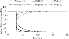
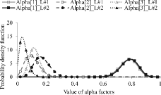
Figure 15. The update of global alpha factors.

Figure 15. The update of global alpha factors.

Reprints and Corporate Permissions

Please note: Selecting permissions does not provide access to the full text of the article, please see our help page How do I view content?

To request a reprint or corporate permissions for this article, please click on the relevant link below:

Academic Permissions

Please note: Selecting permissions does not provide access to the full text of the article, please see our help page How do I view content?

Obtain permissions instantly via Rightslink by clicking on the button below:

If you are unable to obtain permissions via Rightslink, please complete and submit this Permissions form. For more information, please visit our Permissions help page.