618
Views
7
CrossRef citations to date
0
Altmetric
Technical Material

An improved Feynman-α analysis with a moving–bunching technique

, , , , &
Pages 1647-1652 | Received 25 Mar 2015, Accepted 24 Nov 2015, Published online: 08 Jan 2016

Figures & data

Figure 1. Illustration of the conventional bunching procedure.

Figure 1. Illustration of the conventional bunching procedure.

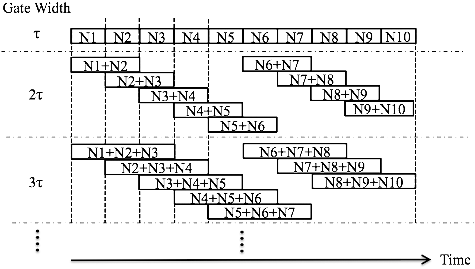
Figure 2. Illustration of the present bunching procedure.

Figure 2. Illustration of the present bunching procedure.

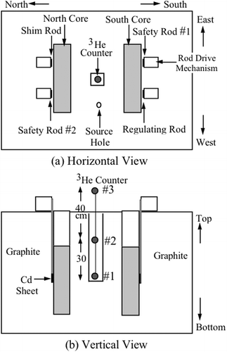
Figure 3. Reactor configuration and detector location.

Figure 3. Reactor configuration and detector location.

Table 1. Control rod patterns employed in the present experiment.

Figure 4. Applicability of different bunching techniques to time-sequence data detected by a neutron counter far from the core at rod pattern A: (a) conventional bunching technique applied; (b) moving–bunching technique applied.
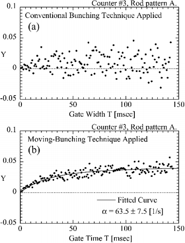
Figure 4. Applicability of different bunching techniques to time-sequence data detected by a neutron counter far from the core at rod pattern A: (a) conventional bunching technique applied; (b) moving–bunching technique applied.

Figure 5. Applicability of different bunching techniques to time-sequence data detected by a neutron counter far from core at rod pattern D: (a) conventional bunching technique applied; (b) moving–bunching technique applied.
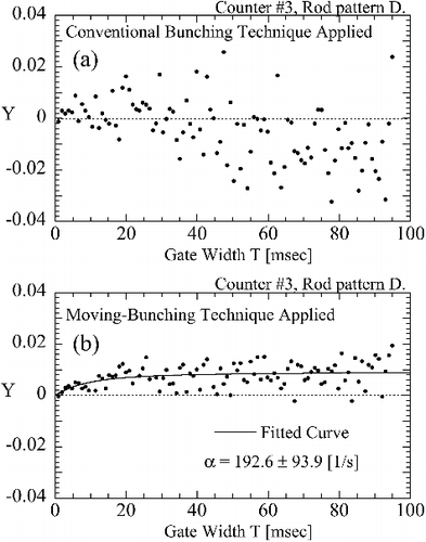
Figure 5. Applicability of different bunching techniques to time-sequence data detected by a neutron counter far from core at rod pattern D: (a) conventional bunching technique applied; (b) moving–bunching technique applied.
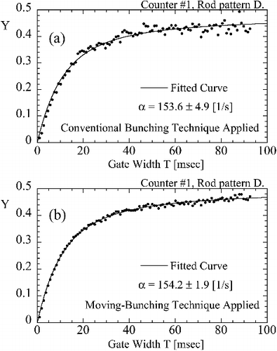
Figure 6. Applicability of different bunching techniques to time-sequence data detected by a neutron counter close to core at rod pattern D: (a) conventional bunching technique applied; (b) moving–bunching technique applied.

Figure 6. Applicability of different bunching techniques to time-sequence data detected by a neutron counter close to core at rod pattern D: (a) conventional bunching technique applied; (b) moving–bunching technique applied.

Table 2. Prompt-neutron decay constant obtained by Feynman-α analysis [1/s].

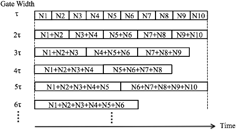
Figure A1. Filtering over (2M + 1) gates.

Figure A1. Filtering over (2M + 1) gates.

Reprints and Corporate Permissions

Please note: Selecting permissions does not provide access to the full text of the article, please see our help page How do I view content?

To request a reprint or corporate permissions for this article, please click on the relevant link below:

Academic Permissions

Please note: Selecting permissions does not provide access to the full text of the article, please see our help page How do I view content?

Obtain permissions instantly via Rightslink by clicking on the button below:

If you are unable to obtain permissions via Rightslink, please complete and submit this Permissions form. For more information, please visit our Permissions help page.