812
Views
2
CrossRef citations to date
0
Altmetric
Articles

Optimization method to determine mass transfer variables in a PWR crud deposition risk assessment tool

, , &
Pages 1476-1483 | Received 25 Jun 2015, Accepted 20 Nov 2015, Published online: 28 Jan 2016

Figures & data

Figure 1. Centered parameter studies of the effect of (a) particle deposition, (b) out-of-core particle release, (c) in-core non-boiling particle release, and (d) mass transfer coefficient for escape probability of boiling on the cycle core boron mass for Unit A with prior source terms adjustments.
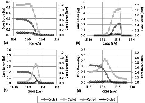
Figure 1. Centered parameter studies of the effect of (a) particle deposition, (b) out-of-core particle release, (c) in-core non-boiling particle release, and (d) mass transfer coefficient for escape probability of boiling on the cycle core boron mass for Unit A with prior source terms adjustments.

Figure 2. Effect of the multiplier on the core boron mass for Unit A. A multiplier value 0.79 effectively “tunes” the unit.
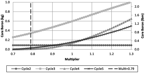
Figure 2. Effect of the multiplier on the core boron mass for Unit A. A multiplier value 0.79 effectively “tunes” the unit.

Table 1. Nuclear steam supply system (NSSS) characteristics of Unit A and Unit B.

Table 2. Plant CIPS history for Unit A and Unit B.

Table 3. Output constraints used for defining convergence criteria.

Table 4. Input constraints used for limiting ranges of possible solution.

Figure 3. Implementation of multilevel optimization. Arrows on the left are input while arrows on the right are collected outputs fed back to the optimizer.
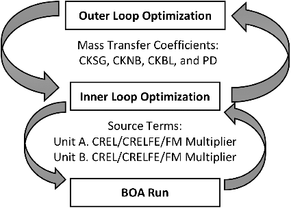
Figure 3. Implementation of multilevel optimization. Arrows on the left are input while arrows on the right are collected outputs fed back to the optimizer.

Figure 4. Illustration of the setup for improving runtime and parallelization, (a) shows the connection mechanism through PBS and MPI calls and (b) shows the thread splitting.
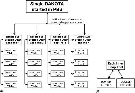
Figure 4. Illustration of the setup for improving runtime and parallelization, (a) shows the connection mechanism through PBS and MPI calls and (b) shows the thread splitting.

Table 5. Mass transfer coefficients after DAKOTA optimization runs.

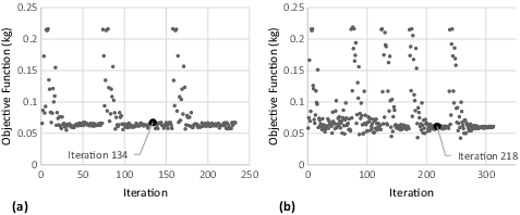
Figure 5. Change in objective function over iteration for (a) Run 1 and (b) Run 2.

Figure 5. Change in objective function over iteration for (a) Run 1 and (b) Run 2.

Table 6. Percentage of constraints met for Unit A.

Table 7. Percentage of constraints met for Unit B.

Table 8. Combined constraint frequency

Figure 6. Unit 2, Cycle 12 core boron difference from CIPS threshold of iterations with 13 constraints met for (a) Run 1 and (b) Run 2.
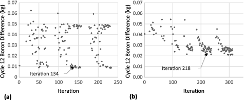
Figure 6. Unit 2, Cycle 12 core boron difference from CIPS threshold of iterations with 13 constraints met for (a) Run 1 and (b) Run 2.

Table 9. Core boron mass comparison.

Reprints and Corporate Permissions

Please note: Selecting permissions does not provide access to the full text of the article, please see our help page How do I view content?

To request a reprint or corporate permissions for this article, please click on the relevant link below:

Academic Permissions

Please note: Selecting permissions does not provide access to the full text of the article, please see our help page How do I view content?

Obtain permissions instantly via Rightslink by clicking on the button below:

If you are unable to obtain permissions via Rightslink, please complete and submit this Permissions form. For more information, please visit our Permissions help page.