Figures & data
Figure 1. Standard axial power and maximum DLOFC temperature profiles for a PBMR-400 core, fuelled with a 16 g/sphere LEU-Th in an OTTO fuelling scheme.
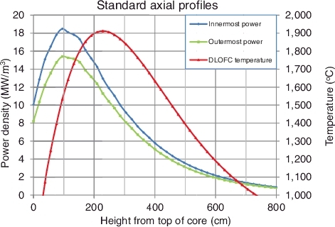
Figure 2. Modified axial power and DLOFC temperature profiles with 10B in the region 115–287 cm of the central reflector.
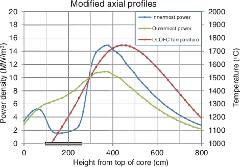
Figure 3. Reactor geometry used for VSOP simulation with the B-10 placement.
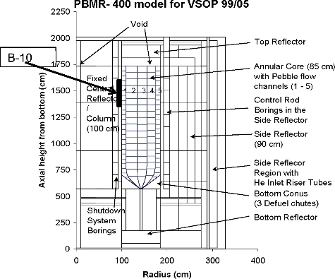
Figure 4. Modified power and maximum DLOFC temperature profiles with a 10B concentration of 6.75 × 10⁻⁶ atoms/(barn.cm) in the central reflector in the height-range of 172 and 345 cm below the top of the fuel core in order to reduce the maximum DLOFC temperature of the symmetric core.
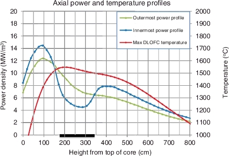
Figure 5. A symmetric maximum DLOFC temperature peak, achieved by modifying the power profiles with a 10B concentration of 6.75 × 10⁻⁶ atoms/(barn.cm) in the suppression region of the central reflector and a 10B concentration of 0.544 × 10⁻⁶ atoms/(barn.cm) in a 57 cm region above the suppression zone, in order to further reduce the maximum DLOFC temperature of the symmetric core.
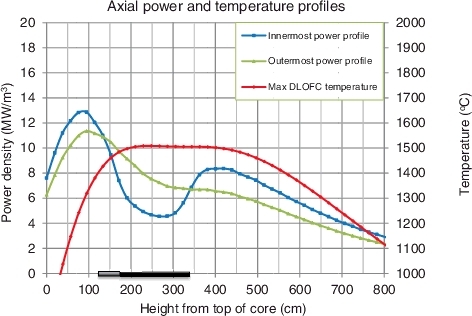
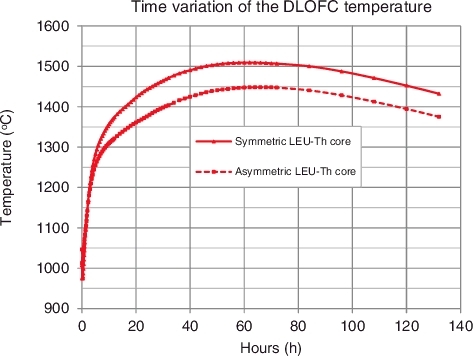
Figure 6. Axial power and maximum DLOFC fuel temperature profiles for producing a lower maximum DLOFC temperature, shown on a separate scale, for both the radially symmetric and asymmetric LEU-Th fuel cycles.
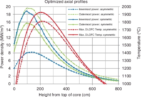
Figure 7. The asymmetric core with modified power and temperature profiles with a 10B concentration of 6.75 × 10⁻⁶ atoms/(barn.cm) in the suppression region of the central reflector and a 10B concentration of 0.544 × 10⁻⁶ atoms/(barn.cm) in a 57 cm region above the suppression, to further reduce the maximum DLOFC temperature of the asymmetric core.
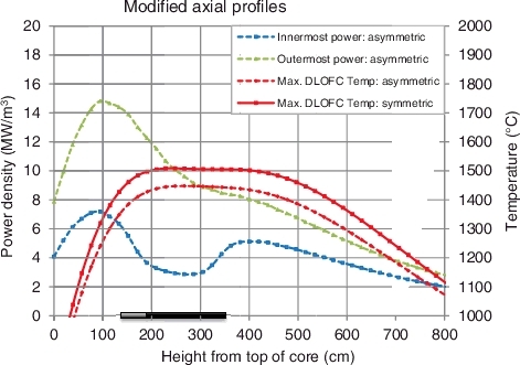
Figure 8. Time profiles for maximum DLOFC temperatures with a 10B concentration of 6.75 × 10⁻⁶ atoms/(barn.cm) in the suppression region of the central reflector and a 10B concentration of 0.544 × 10⁻⁶ atoms/(barn.cm) in a 57 cm region above the suppression zone.