
Figures & data
Figure 1. Schematic of ABWR reactor building.
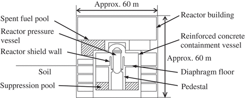
Figure 2. Examples of SSI analysis models.
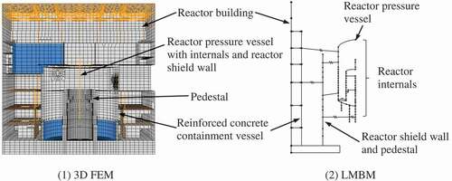
Figure 3. 3D FEM of primary structures for AP1000.
Reprinted from Nuclear Engineering and Design, 237, Tuñón-Sanjur L. et al., Finite element modeling of the AP1000 nuclear island for seismic analyses at generic soil and rock sites, 1474–1485, Copyright (2007), with permission from Elsevier.
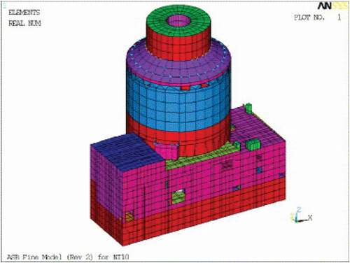
Figure 4. LMBM of substructures for AP1000.
Reprinted from Nuclear Engineering and Design, 237, Tuñón-Sanjur L. et al., Finite element modeling of the AP1000 nuclear island for seismic analyses at generic soil and rock sites, 1474–1485, Copyright (2007), with permission from Elsevier.
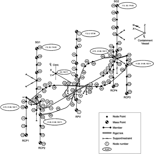
Figure 5. 3D FEM of multi-axis loading tests on RC shear walls.
Reprinted from Nuclear Engineering and Design, 295, Syed S. and Gupta A., Seismic fragility of RC shear walls in nuclear power plant part 2: Influence of uncertainty in material parameters on fragility of concrete shear walls, 587–596, Copyright (2015), with permission from Elsevier.
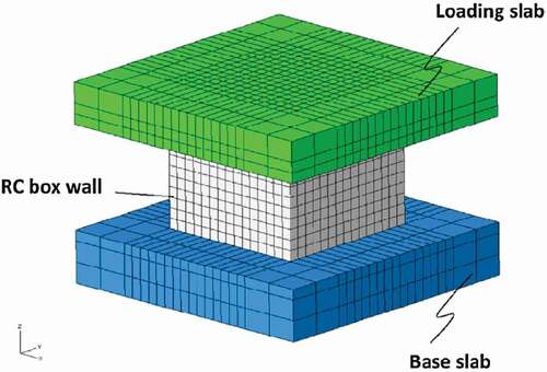
Figure 6. 3D FEM of reactor pressure vessel.
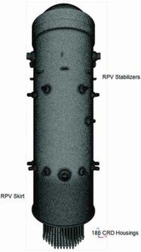
Figure 7. 3D FEM of Hualien large-scale seismic test.
Reprinted from Nuclear Engineering and Design, 295, Kabanda J. et al., Time and frequency domain analyses of the Hualien large-scale seismic test, 261–275, Copyright (2015), with permission from Elsevier.
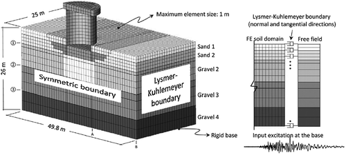
Figure 8. 3D FEM of containment structure.
This figure is reprinted under the terms of the Creative Commons Attribution 4.0 International License (http://creativecommons.org/licenses/by/4.0/).
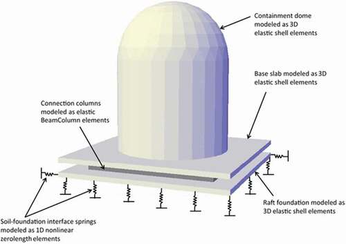
Table 1. Key directions for future studies