Figures & data
Figure 1. Experimental apparatus.
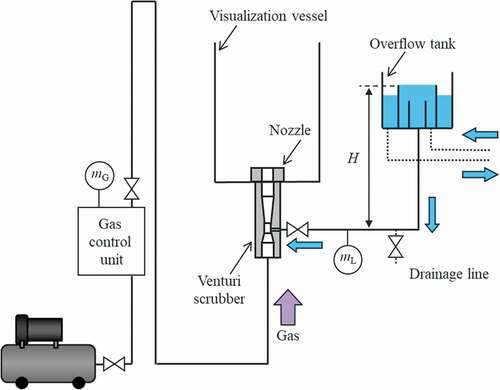
Figure 2. Positional relationship of experimental apparatus and optical system.
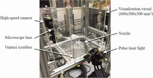
Figure 3. Position of visualized area according to proposed measurement method.
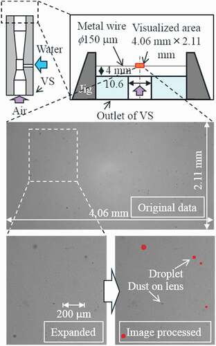
Figure 4. Exposure time setup.
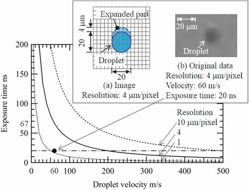
Figure 5. Series of snapshots obtained using proposed image processing scheme.
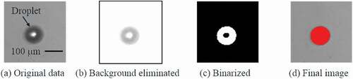
Figure 6. Relationship among gas velocity, liquid velocity, and liquid-gas ratio.
Figure 7. Superimposed images of droplets measured in 100 snapshots at superficial gas velocities of 83–292 m/s.
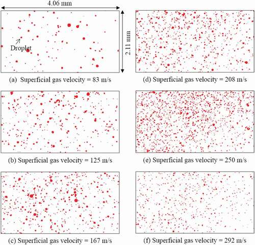
Figure 8. Droplet diameter distributions at superficial gas velocities of 83–292 m/s.
Table 1. Relative error
Table 2. Constant values in gamma distribution (EquationEquation (8)(8)
(8) )
Figure 9. Evaluation of SMD.
Figure 10. Positions of each visualized area in –.
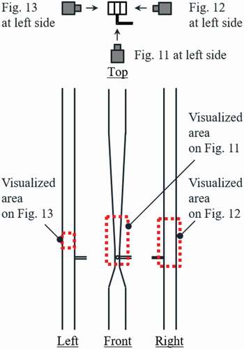
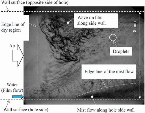
Figure 11. Front view of hydraulic behavior at each gas velocity.
Figure 12. Side view of hydraulic behavior at each superficial gas velocity.
Figure 13. Local snapshot of hydraulic behavior in diffuser part.