Figures & data
Figure 1. Resistivity of Glass as a function of temperature for SiO2-Na2O-TiO2-Fe2O3-based glass
Figure 2. Industrial-scale JHCM used for experiments (a) Start-up heating using plenum heaters; (b) Electrode heating
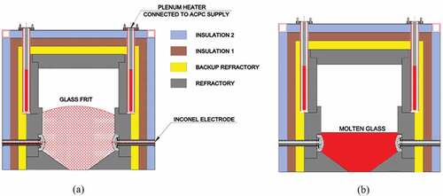
Table 1. Physical properties of glass and insulation materials used for modelling
Figure 3. Heat apportionment of start-up heating
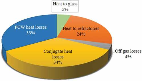
Figure 4. Schematic of experiment used for determination of the mode of heat transfer
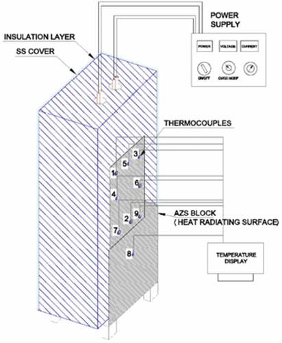
Figure 5. Temperature profiles of thermocouples 5, 2 and 8 for different meshes (coarse, normal, fine, and extra-fine)
Figure 6. Fine mesh view of the model
Figure 7. Validation of model with experimental data
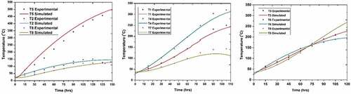
Figure 8. Simulated PH Temperature contours (Rainbow Legend – Celsius scale)
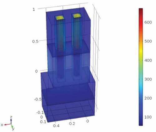
Figure 9. Off-gas ingression and heat losses vs Negative pressure in the melter
Figure 10. (a) Prefabricated square slots for placing of PH with a gap 6–26 mm. (b) Circular Slots for placing of PH
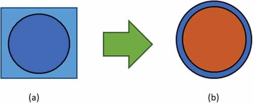
Figure 11. 3D Volume Plot depicting Temperature in K (Rainbow Legend – Celsius scale) for different air gaps
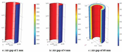
Figure 12. 3D Volume Plot depicting Heat flux in W.m-2 (Rainbow – Celsius scale) for different air gaps
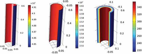
Figure 13. (a) Total Energy Flux Vs Thickness of the air gap; (b) Change in temperature with time for different air gap thickness between refractories and Kanthal© tubes
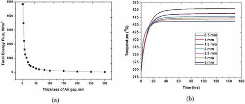
Figure 14. Prefabricated for placing of plenum heaters (a) circular slots; (b) Square slots
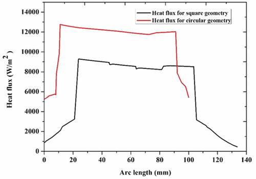
Figure 15. Heat flux vs Distance in the prefabricated in the square and circular design0073