Figures & data
Table 1. Chemical compositions and pHs of the initial HyBRID process solution and spent process solution
Figure 1. The changes in (a) concentration of dissolved Fe ions; (b) dissolution rate of magnetite; (c) pH; (d) concentration of chemical species of hydrazine during dissolution in the existing HyBRID process solution.
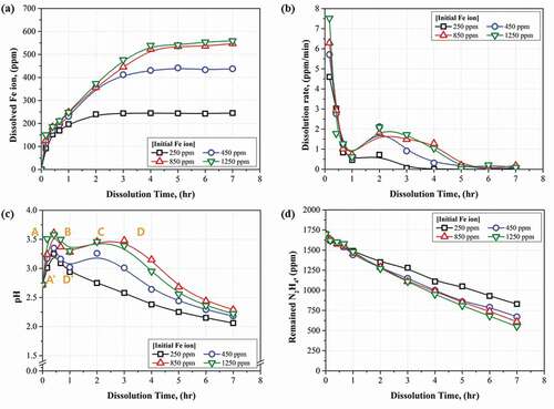
Figure 2. Results of equilibrium calculations on the precipitation step in the recycling process using Ba(OH)2.
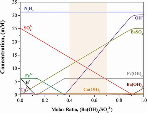
Table 2. Concentrations of metal ions and pH in the purified process solution after the precipitation and filtration steps
Figure 3. Changes in the colors of the solutions during the recycling with changes in the molar ratio of Ba(OH)2/SO42−.
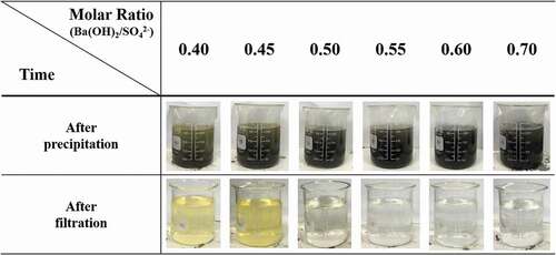
Table 3. Injection amount of decontamination reagents for reducing the purified to the initial condition
Figure 4. Process flow diagram of the PHWR decontamination using the recycled HyBRID solution.
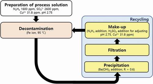
Figure 5. Comparison of Fe ion concentration after dissolution of Fe3O4 using initial HyBRID process solution and the recycled process solution.
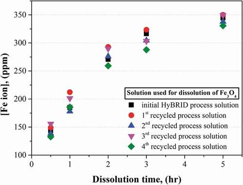
Figure 6. Scheme of the decontamination process of the heat transfer system in the PHWR including recycling process and pH monitoring method.
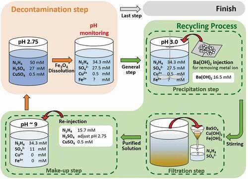
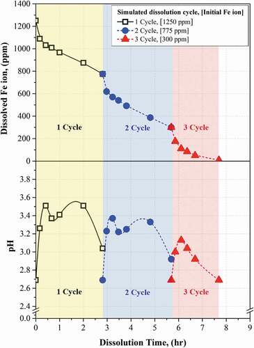
Figure 7. Result of simulated magnetite dissolution test using HyBRID decontamination process for PHWR and monitoring method.