Figures & data
Figure 1. Conceptual design of SAS4A.
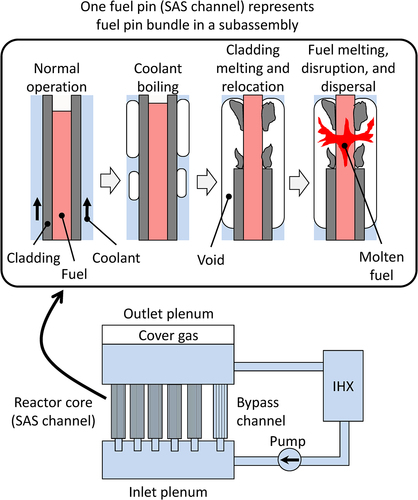
Figure 2. General physical phenomena during the initiating phase. The red and blue frames indicate positive and negative reactivity respectively. In the large/medium SFRs, the physical phenomena that cause the positive and negative reactivities described in the upper part of the figure occur. In the small SFRs, the physical phenomena that cause the negative reactivities described in the lower part of the figure occur.
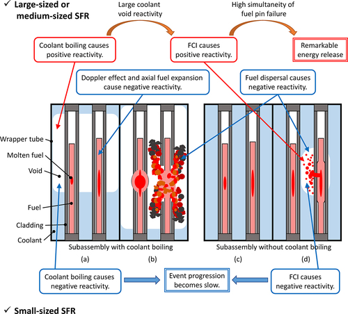
Figure 3. Core layout and channel arrangement for SAS4A code.
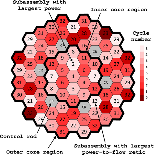
Table 1. Comparison of main specifications with typical medium SFR.
Figure 4. Axial distribution of void coefficient of reactivity of representative SAS channel.
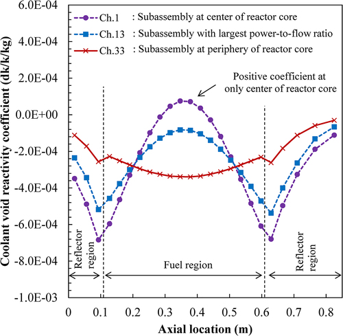
Figure 5. Normalized coolant inlet flow rate in ULOF.
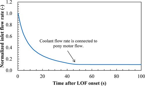
Figure 6. Control rod withdrawal reactivity in UTOP.
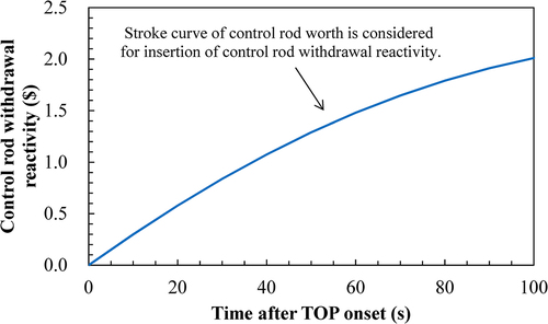
Table 2. Uncertainty considered in uncertainty case.
Figure 7. Transition of total reactivity and normalized power under ULOF reference condition.
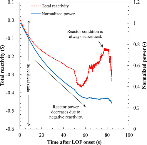
Figure 8. Transition of reactivity under ULOF reference condition.
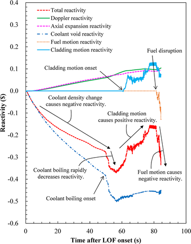
Figure 9. Transition of the total reactivity for the uncertainty cases of Doppler reactivity, axial expansion reactivity, and coolant void reactivity in ULOF.
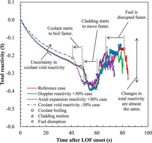
Figure 10. Transition of the total reactivity for the uncertainty cases of cladding motion and fuel motion in ULOF.
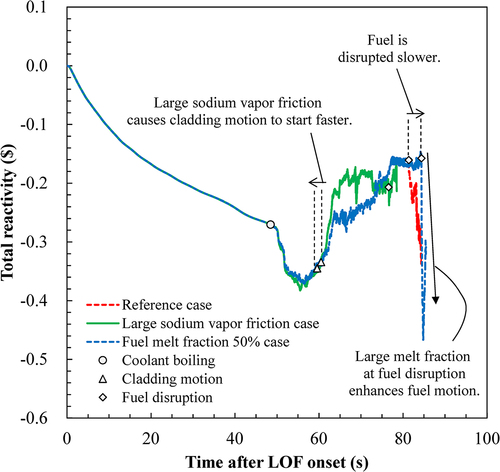
Figure 11. Transition of total reactivity and normalized power under UTOP reference condition.
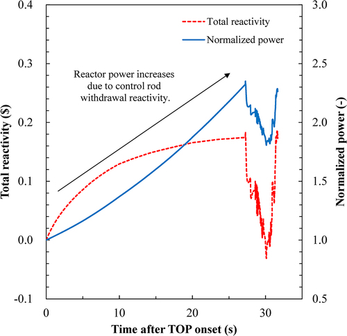
Figure 12. Transition of reactivity under UTOP reference condition.
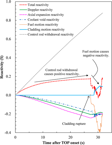
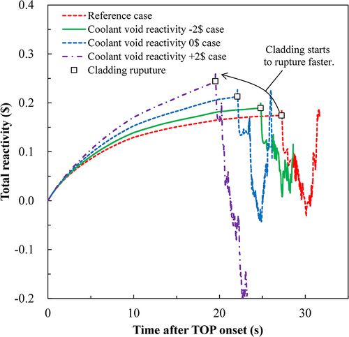
Figure 13. Transition of the total reactivity for the uncertainty cases of Doppler reactivity, axial expansion reactivity, and coolant void reactivity in UTOP.
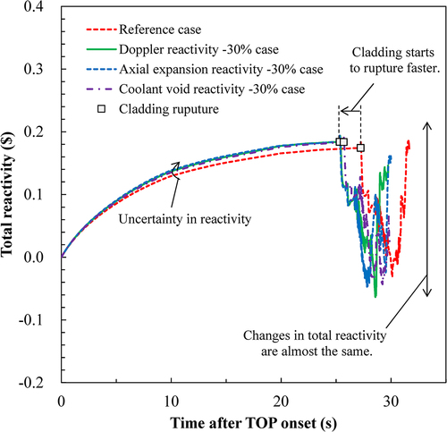
Figure 14. Transition of the total reactivity for the uncertainty cases of the failure criteria in UTOP..
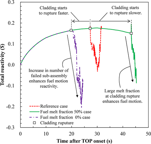
Figure 15. Transition of the total reactivity for the parametric cases of the coolant void reactivity in ULOF.
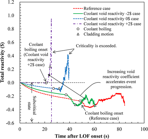
Figure 16. Transition of reactivity in ULOF coolant void reactivity 0$ case.
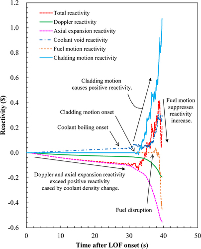
Figure 17. Transition of the coolant void and the cladding motion reactivity for the parametric cases of the coolant void reactivity in ULOF.
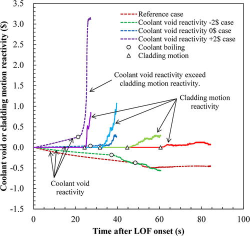
Figure 18. Transition of the total reactivity for the parametric cases of the coolant void reactivity in UTOP.