Figures & data
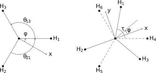
Figure 1. A visual representation of the Euler angles. (a) The first two Euler angles ϕ and θ which are essentially angles defining the spherical coordinates. The first rotation of ϕ is about the z-axis of both the RF- and BF-frame which initially coincide. The BF-frame is then rotated by θ about the y-axis of the BF-frame or the -axis of the figure. (b) The final Euler angle χ is due to a rotation about the z-axis of the BF-frame or the
-axis of the figure.
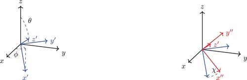
Figure 2. The bond vector BF-frame for the ABA molecule with the x-axis parallel to the A–B bond and the y-axis in the plane of the three atoms. The axes are offset for clarity.
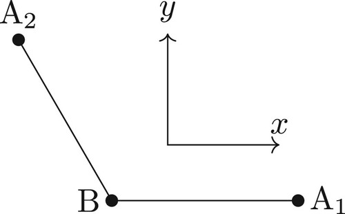
Table 1. The transformation of the t and s vectors.
Table 2. The transformation of in the left column and the corresponding transformed vibrational s-vector and vibrational momentum operator.
Table 3. The change in the Euler angles for a given rotation of the BF-frame.
Figure 3. The principal axis system for the ABA molecule in vibrational equilibrium with the z-axis pointing out of the plane and the y-axis bisecting the A1–B–A2 bond. The axes are offset for clarity.
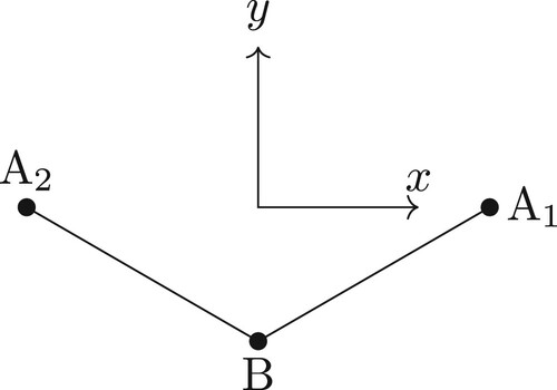
Table 4. The irrep of the function for the MS group
(M) depending on the values of J,
and p.
Figure 4. The structure of the CH3Cl molecule.
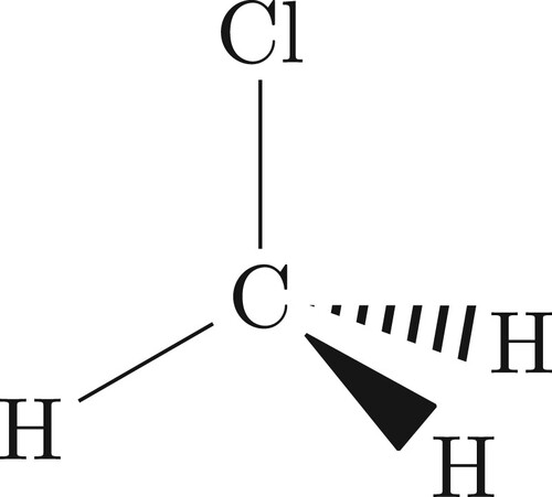
Figure 5. The equilibrium Eckart frame for CH3Cl. The z-axis is along the C–Cl bond and the x-axis in the plane formed by Cl–C–H.
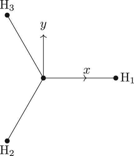
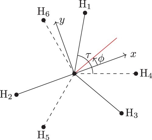
Figure 6. The dihedrals that determine the value of .
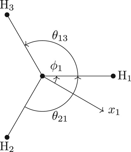
Figure 7. The dihedrals that determine the value of
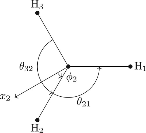
Figure 8. All the angles relevant angles to determine the angle between and
.
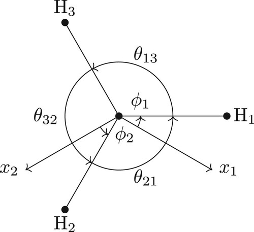
Figure 9. The structure of the C2H6 molecule.
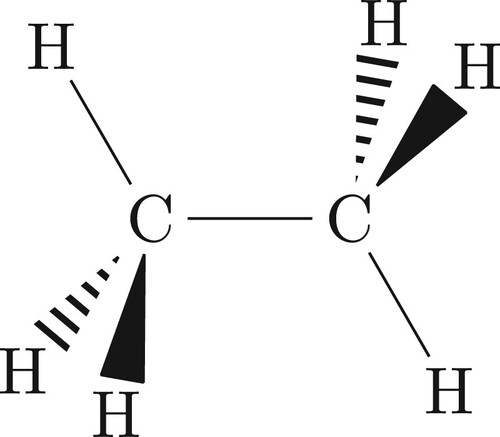
Figure 10. The equilibrium Sayvetz frame for C2H6. The z-axis is parallel to the C–C bond and the x-axis bisects the dihedral between the planes formed by C–C–H and C–C–H
.
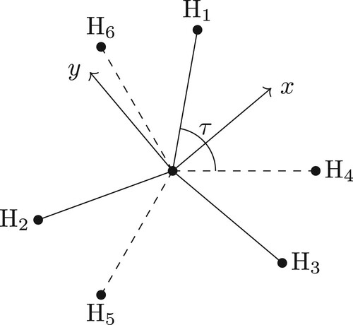
Table 5. The generators of the extended group (EM) of C2H6 and their effect on the torsional angle (τ) and the equivalent rotation of the generator [Citation32].
Figure 11. The geometric frame for C2H6. The z-axis is parallel to the C–C bond. The x-axis is at an angle from the bisector of the dihedral angle between the planes formed by C–C–H
and C–C–H
(colour online).