
Figures & data
Table 1. ff /wm/ion parameters used in this work.
Table 2. Details of the ion-parameters used in this work. σ is the van der Waals radius and ϵ refers to the well depth of the lj interaction.
Figure 1. Definition of the long axis (LA), width (W) and height (H) of the Fab (top) and Fc (bottom) fragments. The coloured spheres show the residues used to calculate the protein dimensions. LA, W and H were obtained from the distance between the centers of mass of those residues.
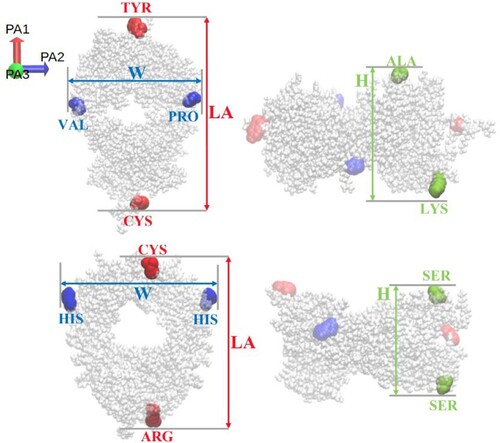
Figure 2. (Left) Initial conformation used for the Fc-Fc PMF calculation. (Right) Snapshot of the protein pair located in a periodic box. The Na (green) and Cl
(purple) ions are also shown. Water is not shown for clarity.
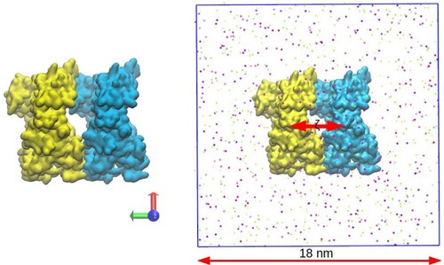
Figure 3. Radius of gyration for the Fab and Fc fragments for different ff/wm/ion parameter combinations.
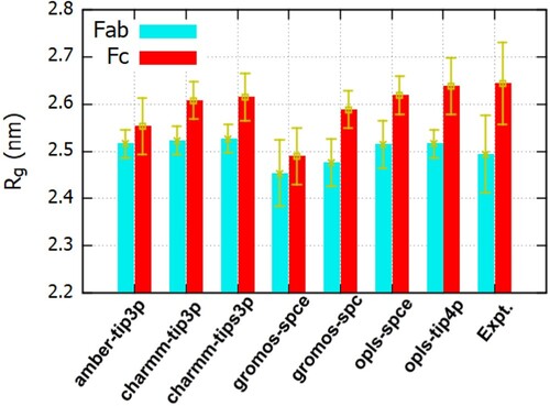
Figure 4. Probability distribution of the radius of gyration of Fab (left panel) and Fc (right panel) fragments for different ff/wm combinations. The average and standard deviations are listed in table S1 of SI.
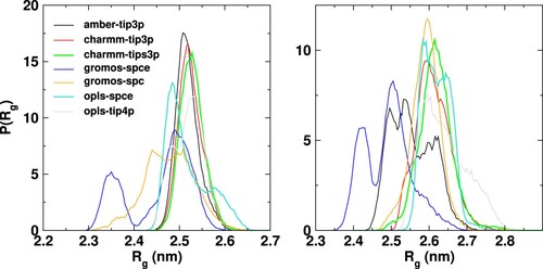
Figure 5. The structure of the Fab fragment corresponding to the two peaks of the R distribution for the gromos-spce system, shown in purple, aligned with the minimised structure of the fab fragment (cyan). The regions that show deviation are highlighted as region I and region II. On the left is a snapshot of the Fab fragment corresponding to the peak at 2.35 nm, aligned with the minimised structure, showing a slight α-helical secondary structure in the terminal region.
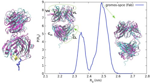
Figure 6. Time series of the R (left y axis) of the Fc fragment for the gromos-spce system. The solvent accessible surface area (SASA) of the hydrophobic amino acids is also shown (see right y axis). The snapshots on the right depict the large amplitude internal motions in the Fc fragment.
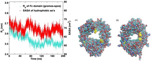
Figure 7. Deviations of the (A) Fab and (B) Fc dimensions, with respect to the crystal structure values, previously used in neutron reflectivity models [Citation52].
![Figure 7. Deviations of the (A) Fab and (B) Fc dimensions, with respect to the crystal structure values, previously used in neutron reflectivity models [Citation52].](/cms/asset/1cac9692-14b3-47ef-85f0-2fd3f94858cc/tmph_a_2236248_f0007_oc.jpg)
Table 3. Dimensions of the Fab fragment for the different systems simulated in this work. The error bars were obtained from calculations performed with the three independent trajectories, for each system. The structure of the Fc domain was taken from pdb id. 1HZH, while the structure of the Fab domain was obtained from Ref. [Citation17].
Table 4. Dimensions of the Fc fragment for the different systems simulated in this work. The error bars are over the averages obtained from the three independent runs performed for each system.
Figure 8. Radial distribution function of water around the (a) Fab and (b) Fc surfaces as a funciton of the distance (r) to the protein surface (r).
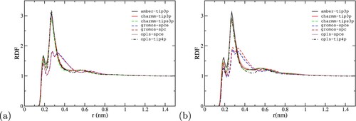
Figure 9. Radial distribution function of Na and Cl
ions around the Fab surface as a functon of the ditance to the protein surface (r). The peak heights of the distributions not shown in full are indicated near the figure labels.
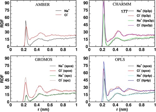
Figure 10. Radial distribution function of Na and Cl
ions around the Fc surface as a function of the distance to the protein surface (r). The peak heights of the distributions not shown in full are indicated near the figure labels.
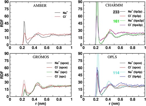
Figure 11. Net charge as a function of distance from the surface (r) of the Fab and Fc fragments for the different systems simulated in this work. The curves have been obtained for the last 100 ns of 200 ns long trajectories and have been further averaged over three independent runs.
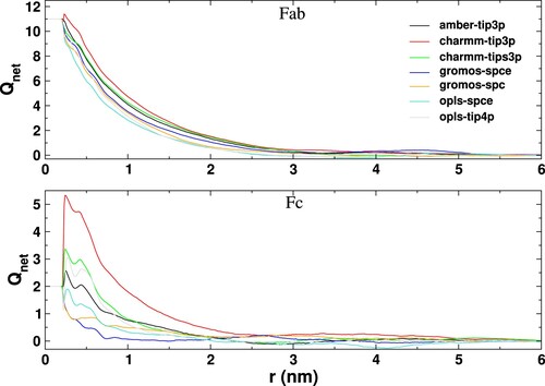
Table 5. Debye length (ζ) obtained by fitting the vs. r plots shown in Figure with the function A
e
.
Figure 12. The Fc-Fc ΔG(r) profiles calculated using the charmm27 (see Figure S12 of SI for additional details) and gromos96 54a7 as a function of the center of mass separation between proteins (see Figure S13 of SI additional details) ff s.
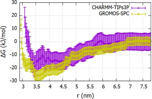
Figure 13. The Fab-Fab ΔG(r) profiles calculated using the charmm27 and gromos96 54a7 ff s as a function of the center of mass separation between proteins.
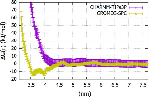
Table 6. Table of B values from simulations and experiments. The results were obtained using the data shown in Figures and .