
Figures & data
Fig. 1. Layout for 1-kW(electric) Kilopower system.
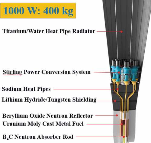
Fig. 2. KRUSTY reactor configuration.
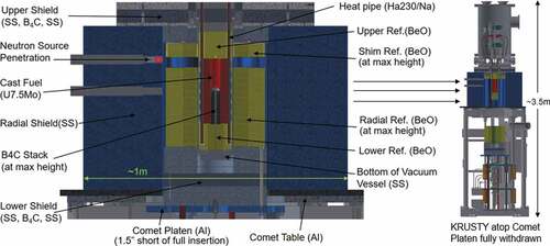
Fig. 3. MCNP core schematic.
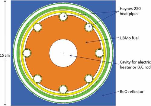
Fig. 4. MCNP schematic of outer core region.
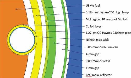
Fig. 5. KRUSTY in-vacuum components.
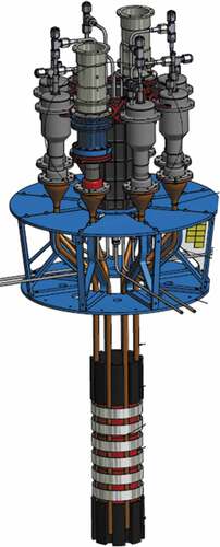
Fig. 6. KRUSTY BeO puzzle pieces, centering ring, and vacuum can, surrounded by radial shield.
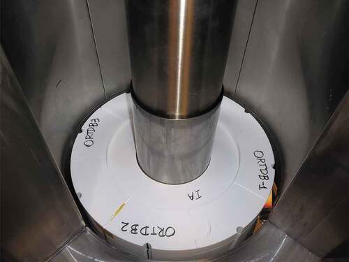
Fig. 7. Design drawing of radial shield.
TABLE I Criticality Calculations for Various Hypothetical Configurations
Fig. 8. The keff versus radial reflector height.
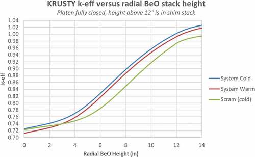
Fig. 9. KRUSTY reactivity versus platen position (with pretest nominal BeO loading).
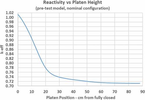
Fig. 10. Component temperature-dependent reactivity worth.
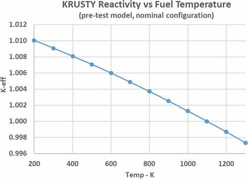
TABLE II Reactivity Feedback of Reactor Components
Fig. 11. Reactivity as a function of heat pipe pool height.
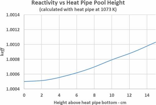
Fig. 12. Axial peaking factor in the KRUSTY fuel.
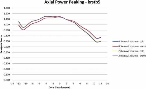
Fig. 13. KRUSTY core temperature calculations at axial center.
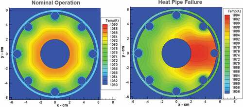
Fig. 14. Systemwide (ex-fuel) power density at 4 kW(thermal).
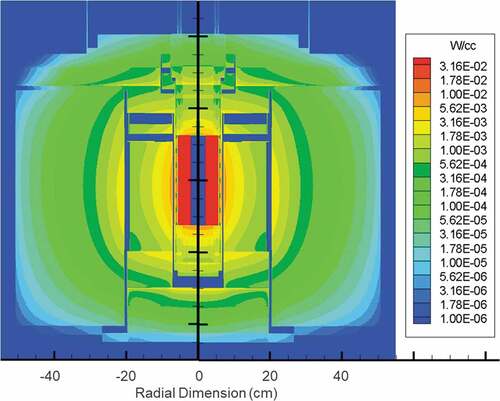
TABLE III System Power Deposition Fractions