Figures & data
Fig. 1. Flowchart illustrating the simplified design process.
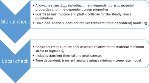
Fig. 2. Stress distribution (normalized to the same maximum value) as a function of position through the section for a simple, rectangular section under bending stress.Citation13
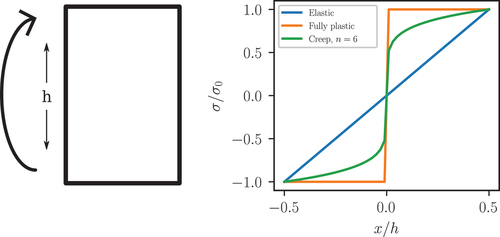
Fig. 3. Sample geometry of a plane strain plate with an array of holes. The black line shows the stress classification line used to calculate the design life via the current ASME rules. The inset shows the periodic unit cell used in the thermal and mechanical simulations as well as typical results from thermal and structural simulations.
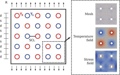
Fig. 4. Results of the design study on the plate with hole geometry: (a) difference in allowable design life as a function of primary load level, (b) difference in allowable design life as a function of thermal stress, and (c) difference in allowable design life as a function of d/s.
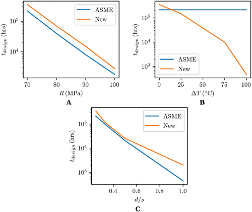
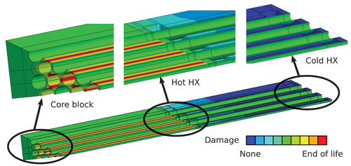
Fig. 5. Overview of the complete finite element model of the test article. Details are called out in three critical areas: the core block, the hot end of the heat exchanger, and the cold end of the heat exchanger.
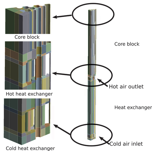
Fig. 6. Fringe plot of the creep damage calculated in the component according to the local service check criteria at 100 000 h. Red regions are near a damage fraction of D = 1, indicating the design life for the component is around 100 000 h.