Figures & data
Fig. 1. Contribution of 235U, 238U, 239Pu, and 241Pu to the total fission neutron emission rate as a function of time in the case of (a) UOX assemblies and (b) MOX assemblies.
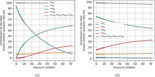
TABLE I Data for Fission Neutron Spectrum Modeling
Fig. 2. Radial cut of the MCNP6 reactor modeling with tallies indicated by black and white sections. (1) Fuel assemblies; (2) core baffle; (3) moderator bypass; (4) core barrel; (5) thermal neutron shield; (6) downcomer; (7) RPV; (8) capsules of the French surveillance program.
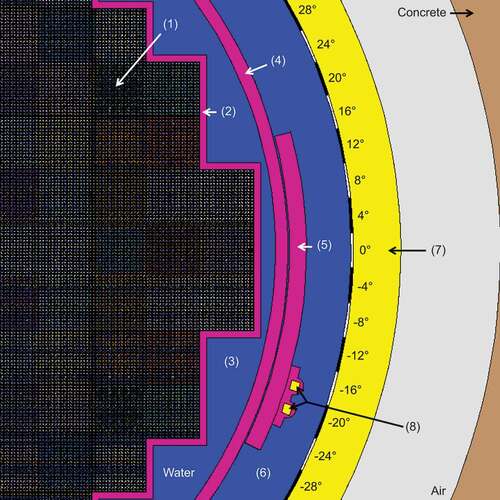
Fig. 3. Axial cut of the MCNP6 reactor modeling and axial segmentation of the considered tallies indicated by black and white sections. (1) Fuel assemblies; (2) core baffle; (3) moderator bypass; (4) core barrel; (5) thermal neutron shield; (6) downcomer; (7) RPV.
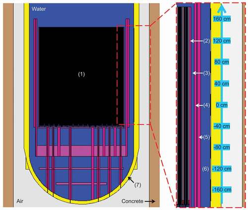
Fig. 4. Radial cut of the MCNP6 (a) UOX assembly and (b) MOX assembly modeling. For MOX assemblies, three different types of fuel pins are modeled with high (orange), medium (pink), and low (red) Pu content.
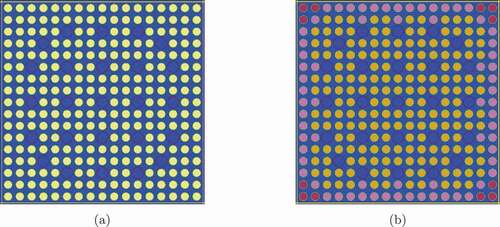
Fig. 5. Atomic displacement cross section of 56Fe processed at 300 K from the JEFF-3.3 nuclear data library and comparison between the NRT-dpa model and the ARC-dpa model.
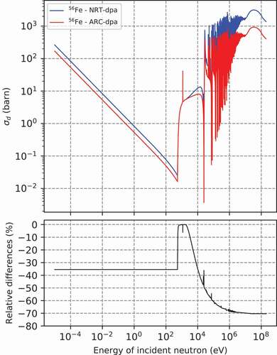
TABLE II Composition of RPV Steel*
TABLE III Material Constants*
Fig. 6. Relative fission neutron emission rate distribution differences (%) between the developed and the reference methodologies at (a) fuel assembly level and at (b) fuel pin level .
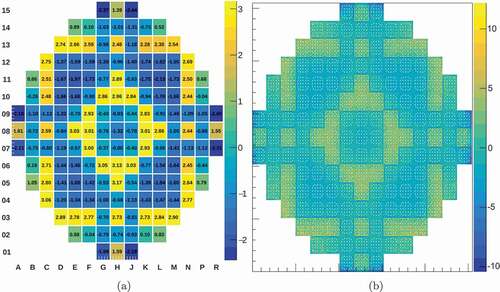
Fig. 7. (a) Fast neutron flux and (b) ARC-dpa axially integrated azimuthal distributions and relative differences between using the SIMULATE5 and MCNP6 fission neutron source terms.
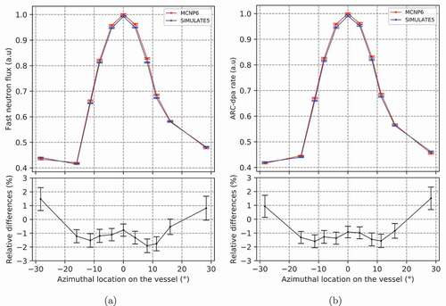
Fig. 8. (a) Fast neutron flux and (b) ARC-dpa axially integrated azimuthal distributions and relative differences between the use of beginning-of-cycle and end-of-cycle fuel compositions in the MCNP6 fixed source calculation.
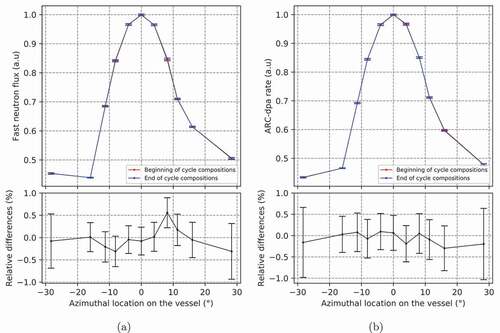
Fig. 9. Relative differences (%) in the cycle-averaged dpa rate distribution on the RPV between the use of a detailed vessel material and the use of a simplified vessel material .
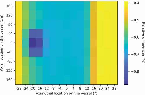
TABLE IV Summary of Methodological Biases on RPV Aging Estimates
Fig. 10. Number of irradiation cycles of each fuel assembly for the considered fuel loading (UOX assemblies are indicated in green, and MOX assemblies are indicated in purple). For symmetry reasons, only a quarter of the core is represented.
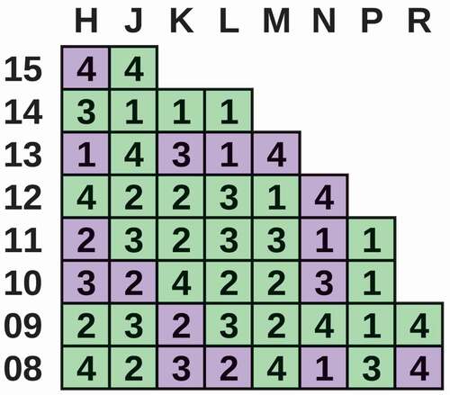
Fig. 11. Evolution along the cycle of (a) the azimuthal fast neutron flux distribution on the RPV (axially integrated) and (b) the axial distribution for azimuthal position 0 deg on the RPV.
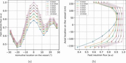
Fig. 12. Relative differences (%) in the cycle-averaged ARC-dpa rate distribution on the RPV between integration methods 1 and 2 .
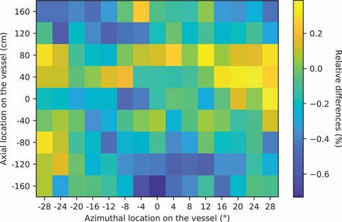
Fig. 13. Relative differences (%) in the cycle-averaged ARC-dpa distribution on the RPV between the temporal mesh a and the temporal mesh b .
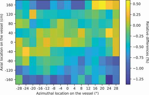
Fig. 14. Relative differences (%) in the cycle-averaged ARC-dpa distribution on the RPV between the temporal mesh a and the temporal mesh c .
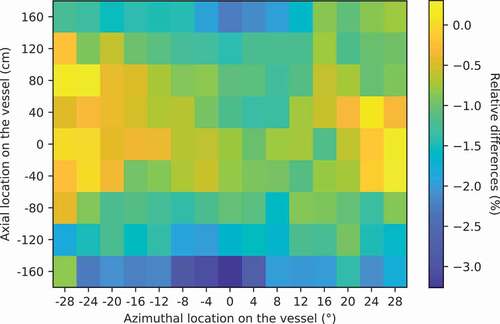
Fig. 15. Contributions of neutron energies to the cycle-averaged, axially integrated, ARC-dpa rate in the capsules and at several azimuthal locations in the RPV, for the reactor cycle described in Sec. III.A.
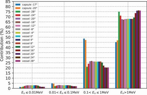
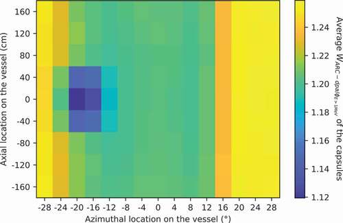
Fig. 16. Cycle-averaged distribution on the vessel for the reactor cycle described in Sec. III.A.