Figures & data
Table 1. Vapour pressure (in Pa) of elements used in ferrous powder metallurgy at different temperatures [Citation10].
Figure 1. PM steel Fe-4%Mn-0.3%C, sintered 10 min at 1120°C (water atomised Fe, electrolytic Mn) [Citation34].
![Figure 1. PM steel Fe-4%Mn-0.3%C, sintered 10 min at 1120°C (water atomised Fe, electrolytic Mn) [Citation34].](/cms/asset/ce636521-a89c-43db-b90c-54914e219379/ypom_a_1886717_f0001_ob.jpg)
Figure 2. Schematic of ‘internal getter’ effect: (a) thermodynamic basis and (b) transfer reaction.
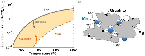
Figure 3. Thermogravimetry and mass spectrometry graphs for (a) Fe-0.5%C and (b) Fe-0.5%C-4%Mn (electrolytic) in Ar atmosphere.
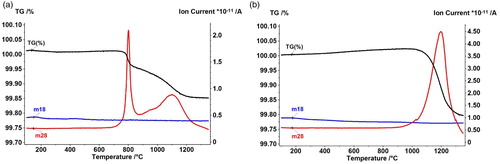
Figure 4. Fe-12%Mn-x%C, compacted at 700 MPa, sintered 60 min at 1400°C, cold rolled. (a) Fe-12%Mn-0.2%C, rolled, after 1 pass. (b) Fe-12%Mn-0.8%C, rolled, after 5 passes.
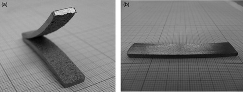
Figure 5. Magnetic saturation, apparent hardness and microhardness of Fe-12%Mn-x%C as sintered and after rolling. Compacted at 600 MPa, sintered 60 min at 1400°C.
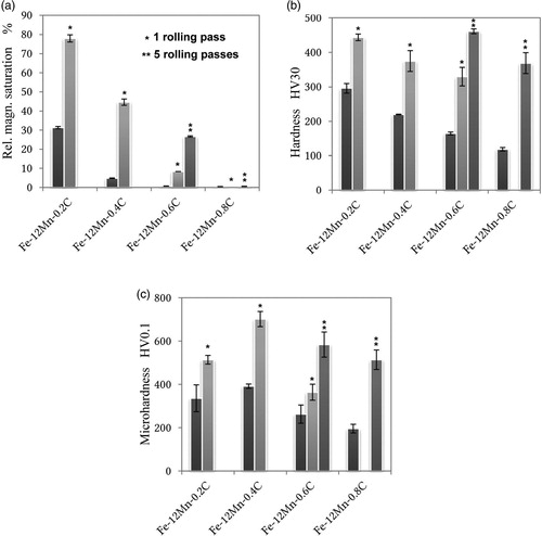
Figure 6. Fe-12%Mn-2.0%C (Carbonyl Fe, electrolytic Mn). (a) Specimen sintered at 1350°C. (b) Dilatometric graph + MS.
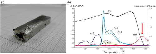
Figure 7. Mn mappings of Fe-10%Mn-0.5%C, sintered 1300°C, prepared from different Fe powders. (a) Atomised iron powder. (b) Carbonyl iron powder.
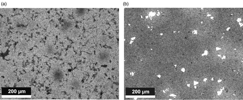
Figure 8. Mn contents after sintering (analysed by WD-XRF) on the surface and core of Fe-9%Mn-0.45 … 0.48%Ccombined, prepared using Fe ASC100.29 and different Mn carriers.
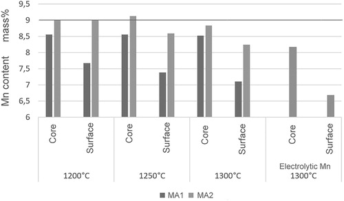
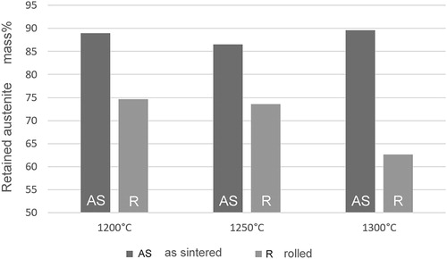
Figure 9. Austenite content, calculated through magnetic saturation, of Fe-9%Mn-0.45 … 0.48%C, prepared using Fe ASC100.29 and MA2 as Mn carrier, as sintered and after rolling (20 fine passes).