Figures & data
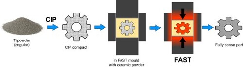
Figure 1. Ellingham diagram showing temperature dependant Gibbs free energy of formation (ΔGf) for various metal oxides over temperature range typically used for FAST processing of Ti powders. Calculated using data from [Citation22,Citation23].
![Figure 1. Ellingham diagram showing temperature dependant Gibbs free energy of formation (ΔGf) for various metal oxides over temperature range typically used for FAST processing of Ti powders. Calculated using data from [Citation22,Citation23].](/cms/asset/e6f4638a-9716-4202-bca8-da35fe667fe4/ypom_a_2236907_f0001_ob.jpg)
Figure 2. Secondary electron micrographs of (a) CP-Ti powder and (b) Ti-6Al-4V powder, (c) measured particle size distribution of both powders.
Table 1. Chemical composition of CP-Ti and Ti-6Al-4V powders used in this study.
Figure 3. Cross-sectional diagram of CIP compact within graphite FAST tooling setup. Dimensions in mm.
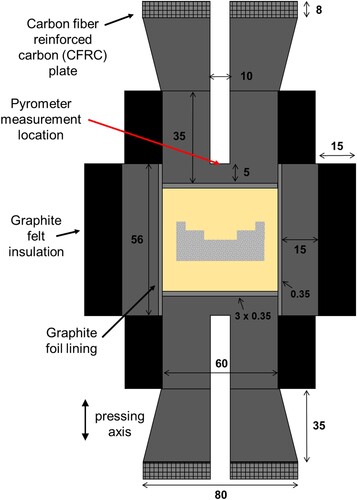
Figure 4. Light micrographs of CIP compact cross section, (a) CP-Ti, (b) Ti-6Al-4V.
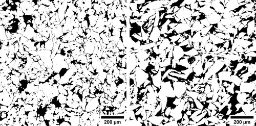
Table 2. Measured Archimedes density and calculated relative density of parts after different processing.
Figure 5. Photographs of CP-Ti and Ti-6Al-4V CIP-FAST parts before and after FAST processing at 980°C for 10 min.
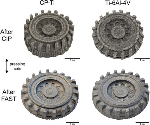
Figure 6. Cross polarised light micrographs of CP Ti and Ti-6Al-4V parts at different locations after FAST processing at 980°C for 10 min.
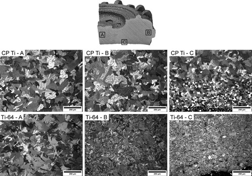
Figure 7. (a–d) Cross polarised light micrographs of Ti-6Al-4V parts (at edge location A from ) with varying dwell time at 980°C. (e) Backscattered electron micrograph of similar region to (d), with corresponding Si X-EDS map and spectra of Si containing phase (f).
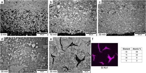
Figure 8. (a) Diagram indicating orientation of CIP compact in FAST tooling, (b) photograph of Ti-6Al-4V compact using higher hardness silicone CIP mould and resulting FAST part after processing at 980°C 30 min, (c) cross polarised light micrograph of Ti-6Al-4V part centre (d + e) edge, (f) backscattered electron micrograph of similar edge region to (e).
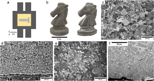
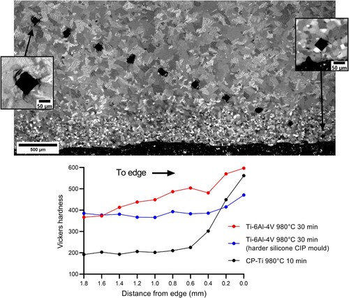
Figure 9. (a) Cross polarised light micrograph of CP Ti part showing Vickers hardness indents towards edge, (b) Vickers hardness values for CP Ti and Ti-6Al-4 V parts towards edge.