
Figures & data
Figure 1. Main image: RGB Sentinel-2 image of Kongsfjorden (27/08/2021) and the surrounding glaciers, the Blomstrandbreen terminus is highlighted by the orange dashed box. Top right inset: Kongsfjorden region relative to the archipelago of Svalbard. Map courtesy of OpenStreetMap contributors data available under Open Database Licence (licenced as CC BY-SA). Bottom left inset: RGB Sentinel-2 (10/09/2021) image of Blomstrandbreen with the final terminus position of each year overlaid from GEEDiT.
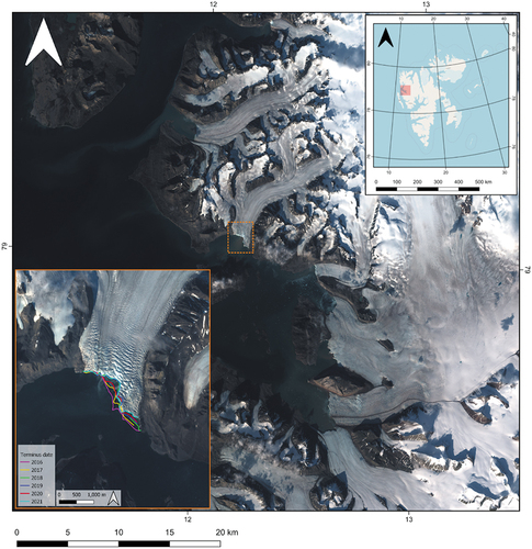
Table 1. Temporal distribution of plumes across the melt season in each year of the study period. Julian days (DOY) are given for first and last observation.
Figure 2. (A) 3 axis bar chart showing the frequency of plumes remaining stable during the study period, while the cumulative plume surface area significantly increases. The left y-axis shows the number of plumes surfacing and the right y-axis (in dark green) is used to show cumulative plume surface area. (b) Histogram shows the distribution of plume sizes which surfaced at Blomstrandbreen between 2016 and 2021. The histogram bin width is 20.
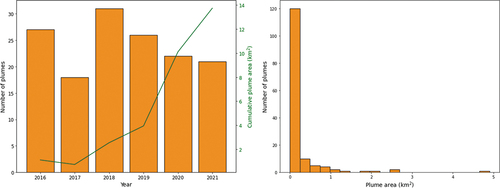
Table 2. Summary of imagery and plume statistics for each year of the study period.
Figure 3. Sentinel-2 images showing the largest sediment-laden meltwater plumes delineated in each year of the study period (2016 – 2021), including an example with the outlines of the plumes delineated in the 2016 image. Dates for each year are as follows, with the Julian day, (DOY) in brackets: 10/07/2016 (192), 10/09/2017 (253), 30/07/2018 (211), 09/07/2019 (190), 27/07/2020 (209), 06/07/2021 (187).
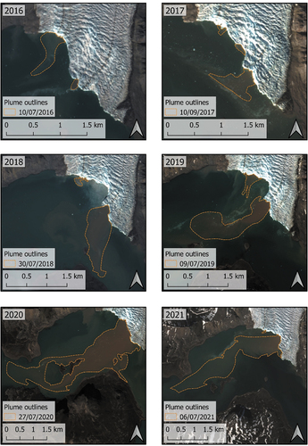
Figure 4. (A) Sentinel-2 RGB image of the lower ablation area of Blomstrandbreen acquired on 14/06/2016, the three main areas where supraglacial lakes (SGLs) form are highlighted by boxes and are shown in panels (b), (c), and (d). (b) SGLs which form in longitudinal foliations created as a result of a tributary glacier flowing into the main branch of Blomstrandbreen. (c) Small SGLs on the eastern margin. (d) a swathe of SGLs which form in longitudinal foliations below the main crevasse field on Blomstrandbreen.
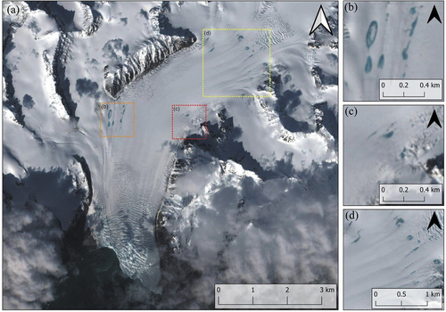
Table 3. Correlation coefficient (Pearson r-value) between meltwater runoff and plume surface area, and rate of terminus change and plume surface area for each year.
Figure 5. Glacial runoff (mm w.E. d−1) and air temperature (℃) at Blomstrandbreen modelled using MAR between 2016 – 2021.
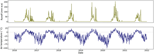
Figure 6. (A) Potential subglacial channel routing beneath Blomstrandbreen using TIGRIF, overlaying a Sentinel-2 RGB image from 27/08/2021, with sediment-laden meltwater plume visible. Overlaid are indicative subglacial channels for k = 0.0, k = 0.5 and k = 1.0. Markers denote the location of a major outlet in 2021 and large bedrock bumps beneath the glacier exposed as a result of recent retreat. (b) Photograph of one of the major channels evacuating sediment-laden water into the fjord from beneath Blomstrandbreen, highlighted by marker on panel (a). (c) Photograph of one of the large bedrock bumps visible beneath the glacier exposed by recent retreat, highlighted by marker on panel (a). (d) Panorama of the western (left) and central (right) portions of the Blomstrandbreen margin, showing sections of ice above the grounding line and exposed bedrock beneath (left) and a separate flow section that remains marine-terminating (far right of image). The markers in panel (a) denote where close ups of the major channel (b) and the bedrock bumps (c) were taken. All photographs in (b), (c) and (d) were taken on 05/07/2021 during fieldwork at Blomstrandbreen.
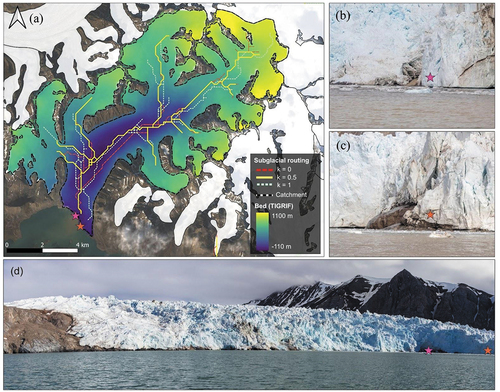
Table 4. Examples of potential supraglacial lake drainages (partial or full) that may link to plume activity throughout the study period. A range is provided for potential drainages and when drainages may impact upon plumes, in most cases, due to the gaps in the availability of cloud-free satellite images. Dates are provided as Julian days (DOY).
Data Availability statement
Terminus, plume and supraglacial lake outlines that support the key findings of this study are available from the corresponding author, [G.D.T], upon request. Regional climate model MAR v3.11.5 data was provided by Dr Xavier Fettweis and is freely available via ftp.climato.be/fettweis. Ice velocity data used in this study are openly available at Service de données de l’Observatoire Midi-Pyrénées at https://doi.org/10.6096/1007.