2,910
Views
196
CrossRef citations to date
0
Altmetric
Original Articles

Validation of a Second-Order Slip Flow Model in Rectangular Microchannels

, &
Pages 23-30 | Published online: 17 Aug 2010

Figures & data

FIG. 1 Experimental setup for the measurement of gaseous microflows.

FIG. 1 Experimental setup for the measurement of gaseous microflows.

FIG. 2 Typical example of volume flow rate measurement.

FIG. 2 Typical example of volume flow rate measurement.

FIG. 3 (a) Top view of the microchannels etched in a silicon wafer (b) and front view of the wafer with its outer connections.
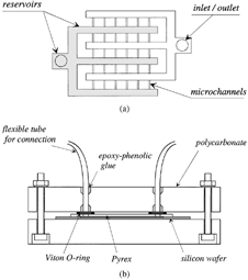
FIG. 3 (a) Top view of the microchannels etched in a silicon wafer (b) and front view of the wafer with its outer connections.

TABLE 1 Characteristics of the tested microchannels

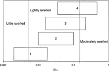
FIG. 4 Range of outlet Knudsen numbers for the experimental data.

FIG. 4 Range of outlet Knudsen numbers for the experimental data.

FIG. 5 Theoretical and experimental mass flow rates. Wafer n°1, 2h = 4.48 μm, T = 294.2 K. a) gas: N2, 0.002 ≤ Kn o ≤ 0.008, P o = 1.9 · 105 Pa; b) same conditions, comparison between plane and rectangular models; c) gas: N2, 0.005 ≤ Kn o ≤ 0.018, P o = 0.82 · 105 Pa.
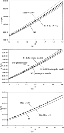
FIG. 5 Theoretical and experimental mass flow rates. Wafer n°1, 2h = 4.48 μm, T = 294.2 K. a) gas: N2, 0.002 ≤ Kn o ≤ 0.008, P o = 1.9 · 105 Pa; b) same conditions, comparison between plane and rectangular models; c) gas: N2, 0.005 ≤ Kn o ≤ 0.018, P o = 0.82 · 105 Pa.

FIG. 6 Theoretical and experimental mass flow rates. Wafer n°2, 2h = 1.88 μm, T = 294.2 K. a) gas: N2, 0.01 ≤ Kn o ≤ 0.017, P o = 2 · 105 Pa; b) gas: N2, 0.027 ≤ Kn o ≤ 0.053, P o = 0.65 · 105 Pa; c) gas: He, 0.029 ≤ Kn o ≤ 0.053, P o = 1.9 · 105 Pa; d) gas: He, 0.05 ≤ Kn o ≤ 0.1, P o = 1.026 · 105 Pa.
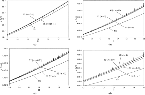
FIG. 6 Theoretical and experimental mass flow rates. Wafer n°2, 2h = 1.88 μm, T = 294.2 K. a) gas: N2, 0.01 ≤ Kn o ≤ 0.017, P o = 2 · 105 Pa; b) gas: N2, 0.027 ≤ Kn o ≤ 0.053, P o = 0.65 · 105 Pa; c) gas: He, 0.029 ≤ Kn o ≤ 0.053, P o = 1.9 · 105 Pa; d) gas: He, 0.05 ≤ Kn o ≤ 0.1, P o = 1.026 · 105 Pa.

FIG. 7 Theoretical and experimental mass flow rates. Wafer n°3, 2h = 1.16 μm, T = 294.2 K. a) gas: N2, 0.016 ≤ Kn o ≤ 0.03, P o = 1.9 · 105 Pa; b) gas: N2, 0.04 ≤ Kn o ≤ 0.09, P o = 0.65 · 105 Pa; c) gas: He, 0.05 ≤ Kn o ≤ 0.09, P o = 1.9 · 105 Pa; d) gas: He, 0.1 ≤ Kn o ≤ 0.22, P o = 0.75 · 105 Pa.
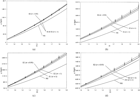
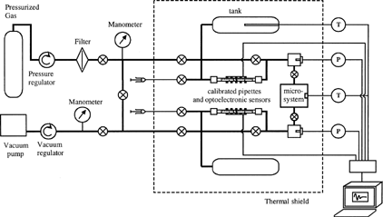
FIG. 7 Theoretical and experimental mass flow rates. Wafer n°3, 2h = 1.16 μm, T = 294.2 K. a) gas: N2, 0.016 ≤ Kn o ≤ 0.03, P o = 1.9 · 105 Pa; b) gas: N2, 0.04 ≤ Kn o ≤ 0.09, P o = 0.65 · 105 Pa; c) gas: He, 0.05 ≤ Kn o ≤ 0.09, P o = 1.9 · 105 Pa; d) gas: He, 0.1 ≤ Kn o ≤ 0.22, P o = 0.75 · 105 Pa.
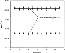
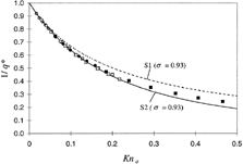
FIG. 8 Inverse reduced flow rate (1/q*) in rectangular microchannels. Comparison of experimental data with 1st and 2nd order slip flow models. Π = 1,8; T = 294,2 K. Wafer n°2 (white), n°3 (grey), n°4 (black). Gas: N2 (circle) and He (square).

FIG. 8 Inverse reduced flow rate (1/q*) in rectangular microchannels. Comparison of experimental data with 1st and 2nd order slip flow models. Π = 1,8; T = 294,2 K. Wafer n°2 (white), n°3 (grey), n°4 (black). Gas: N2 (circle) and He (square).

Reprints and Corporate Permissions

Please note: Selecting permissions does not provide access to the full text of the article, please see our help page How do I view content?

To request a reprint or corporate permissions for this article, please click on the relevant link below:

Academic Permissions

Please note: Selecting permissions does not provide access to the full text of the article, please see our help page How do I view content?

Obtain permissions instantly via Rightslink by clicking on the button below:

If you are unable to obtain permissions via Rightslink, please complete and submit this Permissions form. For more information, please visit our Permissions help page.