
Figures & data
Figure 1. A supercritical CO2 Brayton cycle developed at Brunel University London, UK. (a) Test facility, and (b) Cycle design conditions.
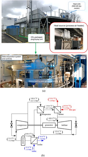
Figure 2. Potential applications relevant to supercritical CO2 Brayton cycle (a) operating temperature range and (b) required operating pressure range. Source data from Reference [Citation10], ARD (advanced reactor designs), ASMR (advanced small modular reactors), GTB (gas turbine bottoming), SP (shipboard propulsion), SHP (shipboard house power), WHR (waste heat recovery), CSP (concentrated solar power), GT (geothermal), IHFF (indirect heating fossil fuel), DHFF (direct heating fossil fuel).
![Figure 2. Potential applications relevant to supercritical CO2 Brayton cycle (a) operating temperature range and (b) required operating pressure range. Source data from Reference [Citation10], ARD (advanced reactor designs), ASMR (advanced small modular reactors), GTB (gas turbine bottoming), SP (shipboard propulsion), SHP (shipboard house power), WHR (waste heat recovery), CSP (concentrated solar power), GT (geothermal), IHFF (indirect heating fossil fuel), DHFF (direct heating fossil fuel).](/cms/asset/b0166250-2fbb-4a6e-8f9a-5bb849ead3a0/uhte_a_2164683_f0002_c.jpg)
Table 1. Developed high temperature and pressure heat exchangers for supercritical CO2 applications.
Figure 3. Typical PCHE (a) flow paths and (b) diffusion-bonded core (courtesy of Heatric Meggitt UK).
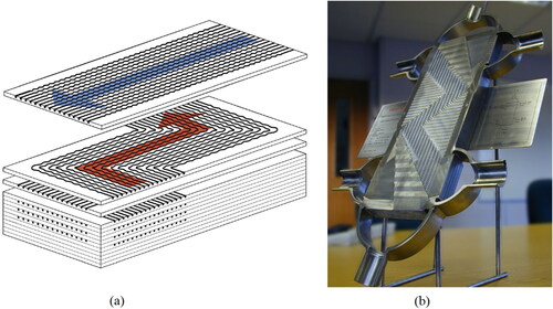
Figure 4. Etched flow paths of PCHEs: (a) straight channel, (b) zigzag (or wavy) channel, (c) channel with S-shaped fins, and (d) channel with airfoil fins.
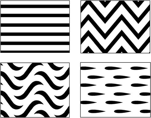
Table 2. Representative studies of thermohydraulic characteristics of supercritical CO2 in printed circuit heat exchanger.
Table 3. Correlations of friction factor and heat transfer during supercritical CO2 flowing in PCHEs.
Figure 5. Microtube heater (courtesy of Reaction Engines Ltd).
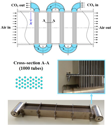
Table 4. Main advantages and drawbacks of developed heat exchangers for supercritical CO2 applications.
Table 5. Main advantages and drawbacks of potential heat exchangers for supercritical CO2 applications.