1,735
Views
10
CrossRef citations to date
0
Altmetric
Articles

Low-speed bending impact behavior of adhesively bonded single-lap joints

&
Pages 1545-1575 | Received 08 Aug 2016, Accepted 16 Nov 2016, Published online: 26 Dec 2016

Figures & data

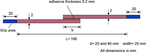
Figure 1. The geometry and dimensions of adhesively bonded single-lap joint.

Figure 1. The geometry and dimensions of adhesively bonded single-lap joint.

Figure 2. Experimental process: (A) bonding apparatus, (B) impact testing apparatus, (C) impact test machine.
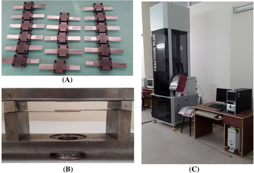
Figure 2. Experimental process: (A) bonding apparatus, (B) impact testing apparatus, (C) impact test machine.

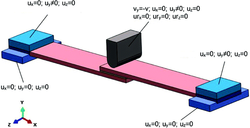
Figure 3. Boundary conditions.

Figure 3. Boundary conditions.

Table 1. Parameters of adhesive (Araldite® 2015) used for CZM.[Citation40]

Table 2. Modulus of elasticity and density values of Al 2024-T3 and Al 5754-0.

Figure 4. Finite element model.

Figure 4. Finite element model.

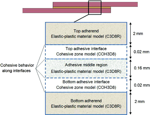
Figure 5. Numerical modeling approach for adhesive and adherends.

Figure 5. Numerical modeling approach for adhesive and adherends.

Figure 6. Stress–strain diagrams of (A) aluminum 2024-T3, (B) aluminum 5754-0 and (C) epoxy adhesive (Araldite® 2015).[Citation24,Citation37]

Figure 6. Stress–strain diagrams of (A) aluminum 2024-T3, (B) aluminum 5754-0 and (C) epoxy adhesive (Araldite® 2015).[Citation24,Citation37]

Figure 7. Experimental and numerical contact force-time and contact force-central deflection diagrams for Al 2024 adhesive single-lap joints.
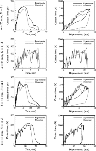
Figure 7. Experimental and numerical contact force-time and contact force-central deflection diagrams for Al 2024 adhesive single-lap joints.

Figure 8. Experimental and numerical contact force-time and contact force-central deflection diagrams for Al 5754 adhesive single-lap joints.
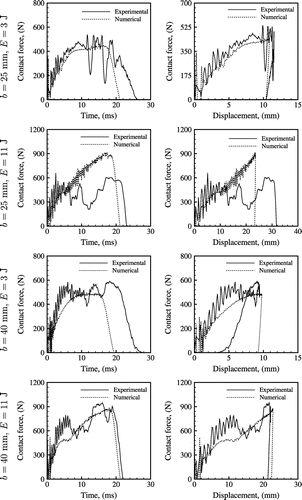
Figure 8. Experimental and numerical contact force-time and contact force-central deflection diagrams for Al 5754 adhesive single-lap joints.

Figure 9. Representation of (A) permanent central deflection , and (B) axial separation length .

Figure 9. Representation of (A) permanent central deflection , and (B) axial separation length .

Figure 10. Experimental (E) and predicted (N) after-impact deformed geometries of the overlap region in Al 2024 adhesive single-lap joints.
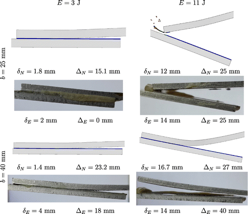
Figure 10. Experimental (E) and predicted (N) after-impact deformed geometries of the overlap region in Al 2024 adhesive single-lap joints.

Figure 11. Experimental (E) and predicted (N) after-impact deformed geometries of the overlap region in Al 5754 adhesive single-lap joints.
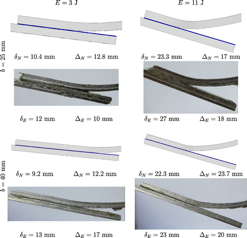
Figure 11. Experimental (E) and predicted (N) after-impact deformed geometries of the overlap region in Al 5754 adhesive single-lap joints.

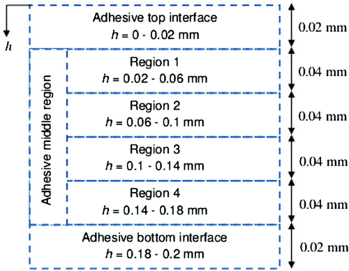
Figure 12. Through-thickness modeling of adhesive layer.

Figure 12. Through-thickness modeling of adhesive layer.

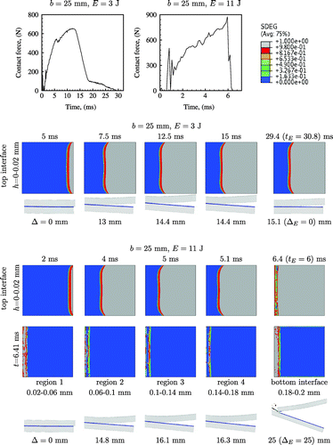
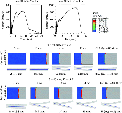
Figure 13. Damage propagation in Al 2024 adhesive single-lap joints ( mm, and 11 J).

Figure 13. Damage propagation in Al 2024 adhesive single-lap joints ( mm, and 11 J).

Figure 14. Damage propagation in Al 2024 adhesive single-lap joints ( mm, and 11 J).

Figure 14. Damage propagation in Al 2024 adhesive single-lap joints ( mm, and 11 J).

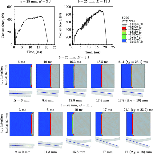
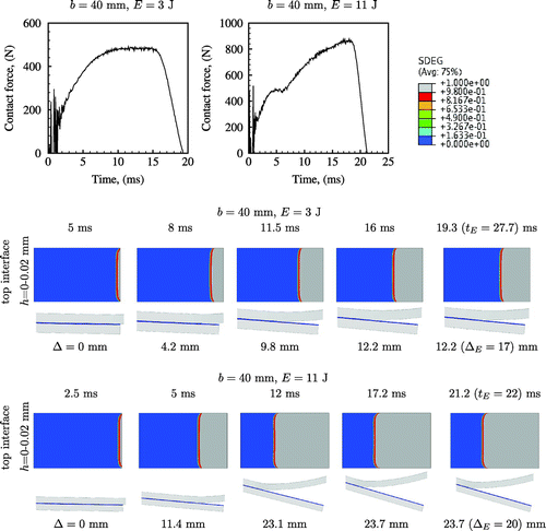
Figure 15. Damage propagation in Al 5754 adhesive single-lap joints ( mm, and 11 J).

Figure 15. Damage propagation in Al 5754 adhesive single-lap joints ( mm, and 11 J).

Figure 16. Damage propagation in Al 5754 adhesive single-lap joints ( mm, and 11 J).

Figure 16. Damage propagation in Al 5754 adhesive single-lap joints ( mm, and 11 J).

Figure 17. SEM and macroscope photographs of adhesive fracture surfaces in Al 2024 adhesive single-lap joint ( mm and J, measurements in m).
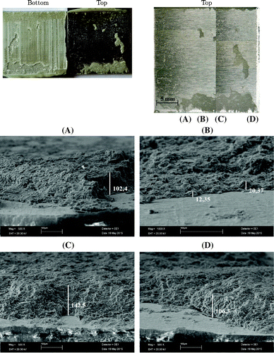
Figure 17. SEM and macroscope photographs of adhesive fracture surfaces in Al 2024 adhesive single-lap joint ( mm and J, measurements in m).
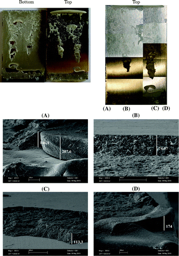
Figure 18. SEM and macroscope photographs of adhesive fracture surfaces in Al 2024 adhesive single-lap joint ( mm and J, measurements in m).

Figure 18. SEM and macroscope photographs of adhesive fracture surfaces in Al 2024 adhesive single-lap joint ( mm and J, measurements in m).

Figure 19. Effect of the overlap length on the contact force histories of adhesive single-lap joints having Al 2024 and Al 5754 adherends.
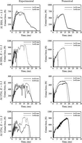
Figure 19. Effect of the overlap length on the contact force histories of adhesive single-lap joints having Al 2024 and Al 5754 adherends.

Figure 20. Fracture surfaces of the top and bottom adherends of Al 2024 and Al 5754 adhesive single-lap joints for different overlap lengths and impact energies.
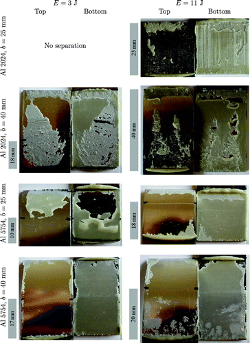
Figure 20. Fracture surfaces of the top and bottom adherends of Al 2024 and Al 5754 adhesive single-lap joints for different overlap lengths and impact energies.
Reprints and Corporate Permissions

Please note: Selecting permissions does not provide access to the full text of the article, please see our help page How do I view content?

To request a reprint or corporate permissions for this article, please click on the relevant link below:

Academic Permissions

Please note: Selecting permissions does not provide access to the full text of the article, please see our help page How do I view content?

Obtain permissions instantly via Rightslink by clicking on the button below:

If you are unable to obtain permissions via Rightslink, please complete and submit this Permissions form. For more information, please visit our Permissions help page.