Figures & data
Fig. 1 Location and land use of the Buriti Vermelho basin.
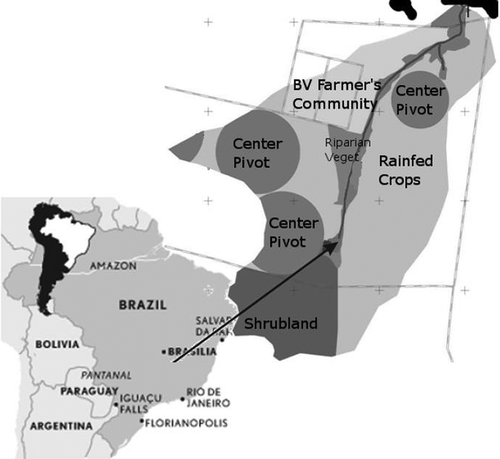
Fig. 2 Location of sensors within the Buriti Vermelho catchment.
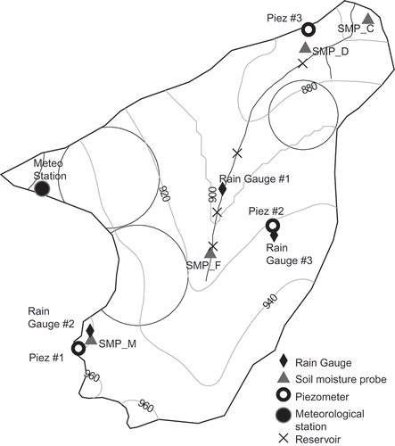
Table 1 Hydrological properties, symbols used and dimensions included in the calibration exercise
Fig. 3 Location and identification number of the pilot points.
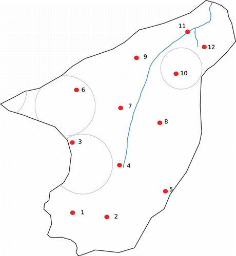
Table 2 Estimated value of the parameters at each pilot point after the calibration. The subscript after the parameter identifies the associated pilot point
Table 3 Comparison of statistics between some estimated hydrological properties and a limited number (n = 9) of laboratory measurements done on random soil cores taken within the BV basin. All average differences are statistically significant
Fig. 4 Parameter fields estimated at the end of the calibration process: (a) overland hydraulic roughness; (b) leakance coefficient at the surface; (c) porosity; (d) horizontal saturated hydraulic conductivity; (e) van Genuchten parameter α; (f) van Genuchten parameter β.
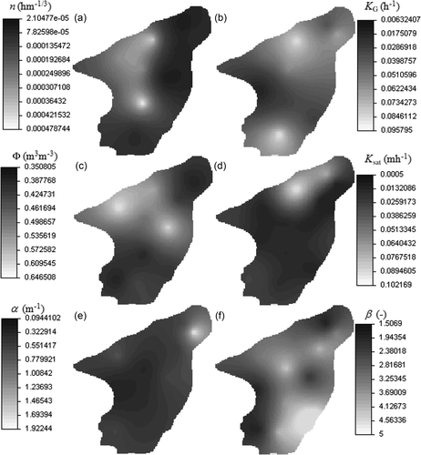
Fig. 5 Measured versus simulated channel flow at the basin outlet (bias = 1.022, mean absolute error = 45.57 m3 h−1, R2 = 0.61); bias is defined as the ratio of simulated average discharge to the observed average discharge (Vivoni et al. 2009). An unbiased simulation has a bias = 1.
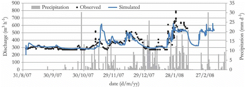
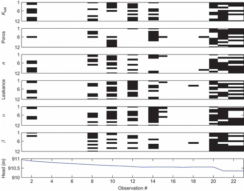
Fig. 6 Measured versus simulated hydraulic heads at Piezometer #2 (bias = 1.29, mean absolute error = 0.196 m, R2 = 0.73); bias is defined as the ratio of simulated average head to the observed average head (Vivoni et al. 2009). An unbiased simulation has a bias = 1. Bias has been calculated setting the reference datum at 910 m. Shaded area is an estimation of the spatial uncertainty of pressure total head (one standard deviation calculated using adjacent cells).
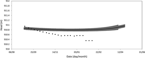
Fig. 7 Measured versus simulated soil moisture content at locations: (a) SMP_D (bias = 0.95, mean absolute error = 0.026, R2 = 0.55), and (b) SMP F (bias = 1.04, mean absolute error = 0.017, R2 = 0.77). Bias is defined as the ratio of simulated average soil moisture to the observed average soil moisture (Vivoni et al. 2009). An unbiased simulation has a bias = 1. Shaded area is an estimation of the spatial uncertainty of soil moisture (one standard deviation calculated using adjacent cells).
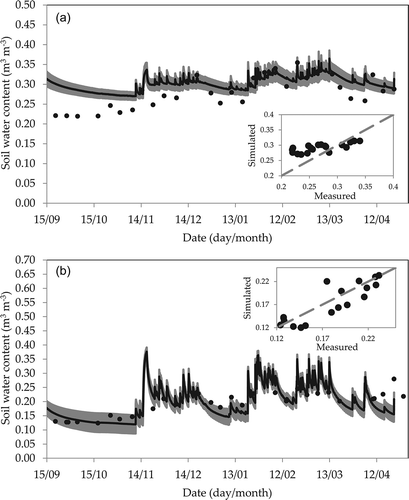
Fig. 8 Composite scaled sensitivity (css) at each pilot point for parameters: (a) Manning's n, (b) leakance, (c) porosity, (d) hydraulic conductivity (log10 of sensitivities), (e) retention curve parameter α and (f) retention curve parameter β. The size of the circle is proportional to the css of the parameter. Square symbol indicates the location of the piezometer; cross symbols indicate the location of soil moisture probes.
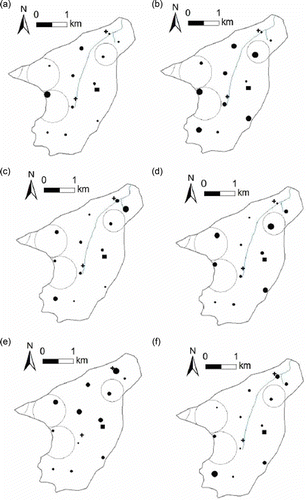
Fig. 9 DFBETA influence graph. Each black dot in the graphs indicates that the associated parameter at the location of the pilot point is influenced by the discharge observation in the bottom graph. A parameter is influenced by an observation when the DFBETA statistic is larger than 2/(ND + NPR)0.5 (see Section 3.7).
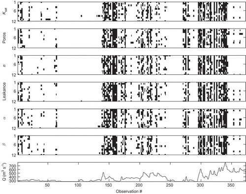
Fig. 11 DFBETA influence graph. Each black dot in the graphs indicates that the associated parameter at the location of the pilot point is influenced by the soil moisture observation in the bottom graph. A parameter is influenced by an observation when the DFBETA statistic is larger than 2/(ND + NPR)0.5 (see Section 3.7).
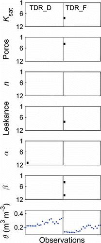
Fig. 10 DFBETA influence graph. Each black dot in the graphs indicates that the associated parameter at the location of the pilot point is influenced by the piezometric observation in the bottom graph. A parameter is influenced by an observation when the DFBETA statistic is larger than 2/(ND + NPR)0.5 (see Section 3.7).