549
Views
27
CrossRef citations to date
0
Altmetric
Original

Image artifacts during MRT hybrid hyperthermia – Causes and Elimination

, , , , &
Pages 327-335 | Received 05 Sep 2007, Accepted 20 Dec 2007, Published online: 09 Jul 2009

Figures & data

Figure 1. The frequency range of the MRI preamplifier is shown. The vertical lines are placed at 15 MHz intervals along the horizontal axis. Below 20 MHz and above 105 MHz there is no more amplification. The maximum amplification is at 60 ± 15 MHz. The marker (⋄) is at 62.8 MHz.
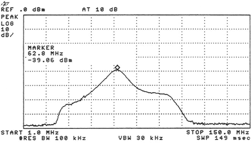
Figure 1. The frequency range of the MRI preamplifier is shown. The vertical lines are placed at 15 MHz intervals along the horizontal axis. Below 20 MHz and above 105 MHz there is no more amplification. The maximum amplification is at 60 ± 15 MHz. The marker (⋄) is at 62.8 MHz.

Figure 2. Transversal (magnitude) images of a patient therapy in the Sigma Eye applicator. The patient was treated in the context of the EORTC study 62961 for a high-risk soft tissue sarcoma of the left thigh. The first picture was taken without power, the second at 800 W and the third at 1400 W amplifier power. The intensity of the streaky artifacts in the magnitude image is strongly dependent on the power used. These artifacts prevent temperature imaging by the image difference method.

Figure 2. Transversal (magnitude) images of a patient therapy in the Sigma Eye applicator. The patient was treated in the context of the EORTC study 62961 for a high-risk soft tissue sarcoma of the left thigh. The first picture was taken without power, the second at 800 W and the third at 1400 W amplifier power. The intensity of the streaky artifacts in the magnitude image is strongly dependent on the power used. These artifacts prevent temperature imaging by the image difference method.

Figure 3. The marker is at 63.3 MHz (imaging frequency), the frequencies of 1–250 MHz are seen on the x-axis, the vertical lines are at 25 MHz intervals. The spectrum was measured with a broadband directional coupler, while the Sigma Eye applicator was attached. The auxiliary frequency of about 8 MHz is clearly seen in (A) together with its mixed frequencies (harmonics) with itself and also with the treatment frequency of 100 MHz. A similar spectrum of frequencies resulted in almost each of the twelve amplifier channels. On measurement of the spectrum by use of an attenuator (dummy load), these auxiliary frequencies were not detected. (B) shows the spectrum of the same channel after the additional installation of a real 50 Ω resistance with a serial inductivity (for more detail see the Appendix) for the adjustment of the auxiliary frequency at approximately 8 MHz.
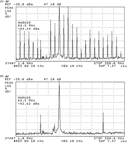
Figure 3. The marker is at 63.3 MHz (imaging frequency), the frequencies of 1–250 MHz are seen on the x-axis, the vertical lines are at 25 MHz intervals. The spectrum was measured with a broadband directional coupler, while the Sigma Eye applicator was attached. The auxiliary frequency of about 8 MHz is clearly seen in (A) together with its mixed frequencies (harmonics) with itself and also with the treatment frequency of 100 MHz. A similar spectrum of frequencies resulted in almost each of the twelve amplifier channels. On measurement of the spectrum by use of an attenuator (dummy load), these auxiliary frequencies were not detected. (B) shows the spectrum of the same channel after the additional installation of a real 50 Ω resistance with a serial inductivity (for more detail see the Appendix) for the adjustment of the auxiliary frequency at approximately 8 MHz.

Figure 4. On the left side the magnitude images are seen for 0 and 900 W power, on the right side the attendant phase images (for PRFS thermometry method). The image interference looks as if the phantom is moving during measurement (which it cannot). The magnitude image shows a clear reduction of the signal, whereby the contours of the picture remain. In the phase image an expansion of phase signal into regions is seen, where no object is present and phase noise should normally be seen (see above the applicator in comparison to the admission without power). The temperature computation, according to the principle of difference to a reference image, is strongly reduced by these image artifacts.
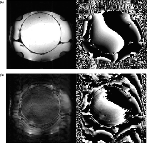
Figure 4. On the left side the magnitude images are seen for 0 and 900 W power, on the right side the attendant phase images (for PRFS thermometry method). The image interference looks as if the phantom is moving during measurement (which it cannot). The magnitude image shows a clear reduction of the signal, whereby the contours of the picture remain. In the phase image an expansion of phase signal into regions is seen, where no object is present and phase noise should normally be seen (see above the applicator in comparison to the admission without power). The temperature computation, according to the principle of difference to a reference image, is strongly reduced by these image artifacts.

Figure 5. The spectrum shows the frequency range from 40 to 110 MHz. The marker (⋄) is at 63.45 MHz. The vertical lines separate frequency ranges of 7 MHz. At 100 MHz still a medium-sized signal of the treatment frequency can be recognized during 1800 W amplifier power, which is clearly weakened by the double pi filters. In addition a very high signal occurs at 50 MHz (A), which varies in intensity and arises in the spectrographic analysis from increasing amplifier power to 900 W. For powers more than 1200 W the signal is nearly continuously present. In (B), despite 1800 W amplifier power, there is no more signal at 50 MHz with filter absorption of −80 dB.
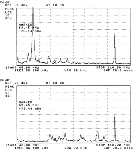
Figure 5. The spectrum shows the frequency range from 40 to 110 MHz. The marker (⋄) is at 63.45 MHz. The vertical lines separate frequency ranges of 7 MHz. At 100 MHz still a medium-sized signal of the treatment frequency can be recognized during 1800 W amplifier power, which is clearly weakened by the double pi filters. In addition a very high signal occurs at 50 MHz (A), which varies in intensity and arises in the spectrographic analysis from increasing amplifier power to 900 W. For powers more than 1200 W the signal is nearly continuously present. In (B), despite 1800 W amplifier power, there is no more signal at 50 MHz with filter absorption of −80 dB.

Figure 6. Spectrum analysis of the two frequency pi-filter for 100 and 50 MHz (in the range 45 to 105 MHz). The attenuation of the whole filter for this frequency is extremely low (0.11 dB). The first marker (1) is at 50 MHz and shows the attenuation of more than −80 dB. Second marker (2) is at the imaging frequency at 64 MHz with nearly no attenuation. The third marker (3) is at the treatment frequency 100 MHz with an attenuation of more than −80 dB.
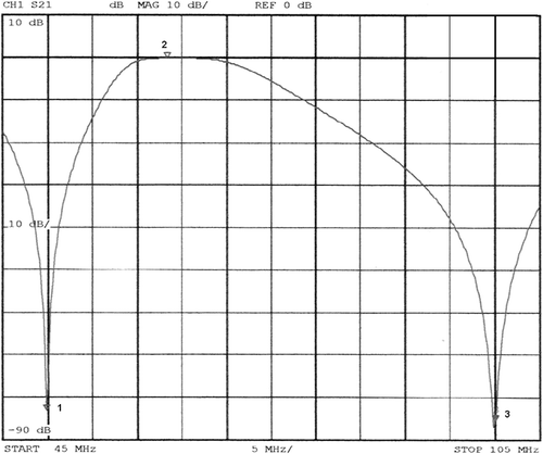
Figure 6. Spectrum analysis of the two frequency pi-filter for 100 and 50 MHz (in the range 45 to 105 MHz). The attenuation of the whole filter for this frequency is extremely low (0.11 dB). The first marker (1) is at 50 MHz and shows the attenuation of more than −80 dB. Second marker (2) is at the imaging frequency at 64 MHz with nearly no attenuation. The third marker (3) is at the treatment frequency 100 MHz with an attenuation of more than −80 dB.

Figure 7. (A) Equivalent circuit diagram of the amplifier (left), as well as the cable run to the antenna of the applicator (on the top right, small box) and the 50 Ω resistance matched with a serial inductivity for 8 MHz (right down). (B) In the insertion loss plot (measured by a Rhode & Schwarz vector analyser) additional attenuation for 8 MHz (black curve) in contrast to the grey curve without this matching can be seen. After employment of the component, almost no more random failures of the power amplifier arose.
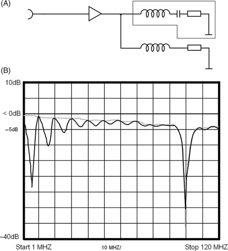
Figure 7. (A) Equivalent circuit diagram of the amplifier (left), as well as the cable run to the antenna of the applicator (on the top right, small box) and the 50 Ω resistance matched with a serial inductivity for 8 MHz (right down). (B) In the insertion loss plot (measured by a Rhode & Schwarz vector analyser) additional attenuation for 8 MHz (black curve) in contrast to the grey curve without this matching can be seen. After employment of the component, almost no more random failures of the power amplifier arose.

Figure 8. Equivalent circuit diagram of the two-frequency pi filter for 100 and 50 MHz. The stubs are installed in a distance of 1/4 λ for 64 MHz (imaging frequency), in order to guarantee as low as possible ripple and a high phase stability in this frequency range. The attenuation of the whole filter for this frequency is only 0.11 dB (see ). The lower capacitance of the filters for 50 MHz was used to achieve a steeper filter effect in this frequency range, to avoid absorbance of the imaging frequency, because this filter is positioned in the transmit-and-receive path of the MRI body coil.
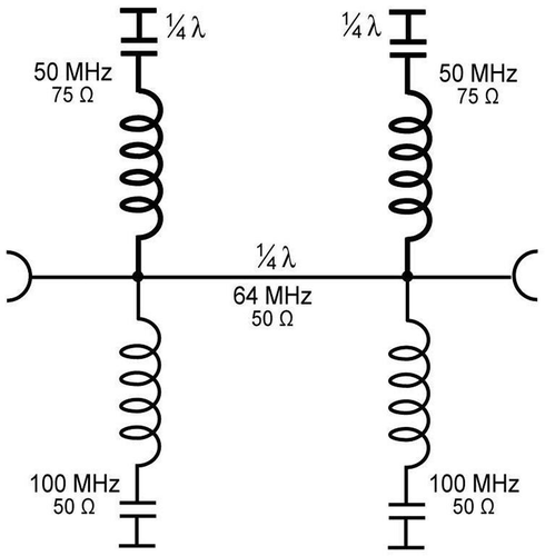
Figure 8. Equivalent circuit diagram of the two-frequency pi filter for 100 and 50 MHz. The stubs are installed in a distance of 1/4 λ for 64 MHz (imaging frequency), in order to guarantee as low as possible ripple and a high phase stability in this frequency range. The attenuation of the whole filter for this frequency is only 0.11 dB (see Figure 6). The lower capacitance of the filters for 50 MHz was used to achieve a steeper filter effect in this frequency range, to avoid absorbance of the imaging frequency, because this filter is positioned in the transmit-and-receive path of the MRI body coil.

Reprints and Corporate Permissions

Please note: Selecting permissions does not provide access to the full text of the article, please see our help page How do I view content?

To request a reprint or corporate permissions for this article, please click on the relevant link below:

Academic Permissions

Please note: Selecting permissions does not provide access to the full text of the article, please see our help page How do I view content?

Obtain permissions instantly via Rightslink by clicking on the button below:

If you are unable to obtain permissions via Rightslink, please complete and submit this Permissions form. For more information, please visit our Permissions help page.