
Figures & data
Figure 1. Floor plan of an MR suite at the author’s institute used for MR-guided microwave ablation. The microwave generator is positioned in the control room which is connected with the scanner room via a cable tunnel. A 6 m coaxial cable is necessary to reach the patient in the centre of the scanner.
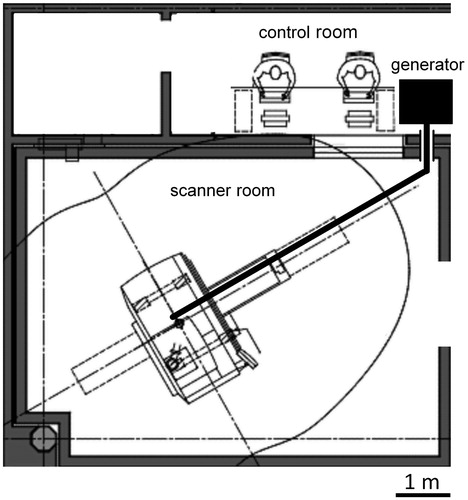
Figure 2. MR-compatible microwave antenna (16–15-LH-15 (MR)) with a 4 cm active tip. The position of the integrated temperature sensor is marked.
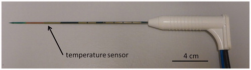
Figure 3. MR-Artefact of the standard (a) and the MR-compatible antenna (b) acquired with a T1-weighted Volumetric Interpolated Breath-hold Examination (T1 VIBE).
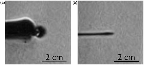
Figure 4. Coagulation zone after 5 min of ablation with the MR-compatible short active tip antenna. Short axis diameter (SA) and long axis diameter (LA) are depicted.
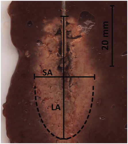
Figure 5. Short axis diameter (a), volume of the ablation zone (b) and energy output (c) after 10 min of ablation time with the [A] Standard antenna, 2 cm active tip, 2.4 m cable, [B] MR-compatible antenna, 2 cm active tip, 2.4 m cable and [C] MR-compatible antenna, 2 cm active tip, extended 6 m cable. Error bars indicate the 95% confidence interval.
![Figure 5. Short axis diameter (a), volume of the ablation zone (b) and energy output (c) after 10 min of ablation time with the [A] Standard antenna, 2 cm active tip, 2.4 m cable, [B] MR-compatible antenna, 2 cm active tip, 2.4 m cable and [C] MR-compatible antenna, 2 cm active tip, extended 6 m cable. Error bars indicate the 95% confidence interval.](/cms/asset/fc1fe0a5-737b-4ac9-ae30-e81226b03026/ihyt_a_1284349_f0005_b.jpg)
Table 1. Comparison of the ablation results of the standard device and the MR-compatible device.
Table 2. Ablation results of both MR-compatible antennas (with short active tip and long active tip) under use of the extended cable.